
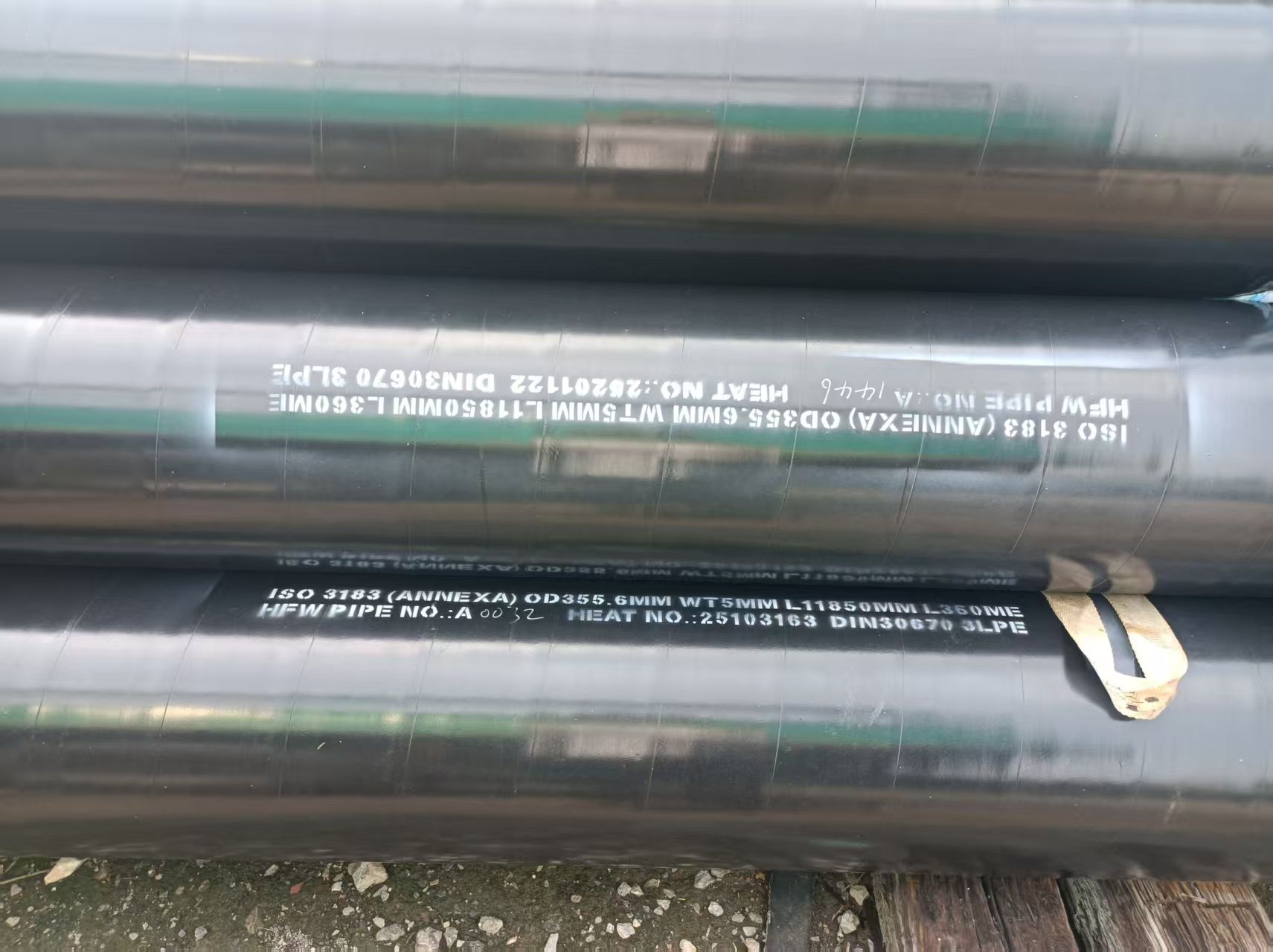
ISO3183 Annex A L360ME line pipe with 3LPE coated for delivery methane gas
ISO3183 Annex A L360ME Line Pipe with 3LPE Anti-Corrosion Coating
PART 1 .
ISO8138 Annex A (normative):PSL 2 pipe ordered for European onshore natural gas transmission pipelines
1.Manufacturing:
If agreed, the manufacturing procedure shall be qualified in accordance with API Spec 5L, 46th edition (2018), Annex B.
2.Steel making
The steel shall be made to a clean steel practice, using either the basic oxygen steel-making process or the electric-arc furnace steel-making process, and shall be fully killed and be made according to fine grain practice.
3.Pipe manufacturing
3-1 Unless otherwise agreed, coil and plate used for the manufacture of welded pipe shall be rolled from continuously (strand) cast or pressure cast slabs. The pipe shall be HFW in the M delivery conditions only as described in API Spec 5L, 46th edition (2018), Table 3.
3-2 For HFW pipe from hot-rolled coil, the pipe forming process ‘cold forming followed by thermomechanical forming’ as described in API Spec 5L, 46th edition (2018), Table 3, shall not be used.
3-3 For HFW pipe, the abutting edges of the coil or plate shall be sheared, milled or machined before welding such that the edges are clean and free of damage.
4.Chemical Composition
|
Steel Grade |
Mass Fraction,Based upon heat and product analyses a % max |
Carbon Equivalentc %Max |
|||||||||
|
Cb |
Si |
Mnb |
P |
S |
V |
Nb |
Ti |
Other |
CEIIW |
CEpcm |
|
|
L290ME |
0.18 |
0.45 |
1.2 |
0.025 |
0.015 |
0.05 |
0.05 |
– |
d |
0.40 |
0.25 |
|
L360ME |
0.18 |
0.45 |
1.3 |
0.025 |
0.015 |
0.05 |
0.05 |
– |
d |
0.40 |
0.25 |
|
a Elements not mentioned in this table shall not be added intentionally without purchaser’s approval except for elements that may be added for deoxidation and finishing of the heat. b For each reduction of 0,01 % below the specified maximum for C, an increase of 0,05 % above the specified maximum for Mn is permissible, up to a maximum increase of 0,20 %. c Based upon product analysis [see API Spec 5L, 46th edition (2018)], 9.2.4 and 9.2.5). The CEIIW limits apply if C > 0,12 % and the CEPcm limits apply if C ≤ 0,12 %. d 0,015 % ≤ Altotal ≤ 0,060 %; N ≤ 0,012 %; Al/N ≥ 2:1, Cu ≤ 0,25 %; Ni ≤ 0,30 %; Cr ≤ 0,30 %; Mo ≤ 0,10 %. |
|||||||||||
5.Mechanical Propertise
|
Steel Grade |
Pipe Body for Welded Pipes |
Weld of HFW Pipes |
|||||
|
Yield Strength Rt0.5 Mpa(psi) |
Tensile Strength Rm Mpa(psi) |
Ratio Rt0.5/Rm |
Elongationa |
Tensile Strength Rm Mpa(Psi) |
|||
|
Min |
Max |
Min |
Max |
Max |
Min |
Min |
|
|
L290ME |
290 (42100) |
440 (63800) |
415 (60200) |
655 (95000) |
0.85 |
21 |
415 (60200) |
|
L360ME |
360 (52200) |
510 (74000) |
460 (66700) |
760 (110200) |
0.85 |
20 |
460 (66700) |
|
a These values apply to transverse test pieces taken from the pipe body. When longitudinal test pieces are tested [see API Spec 5L, 46th edition (2018), Table 20], the values of elongation shall be 2 units higher. |
|||||||
6.Tolerances for diameter, wall thickness, length, and straightness
6-1 Tolerance for diameter and out of roundness
|
Specified outside diameter D mm (in) |
Diameter tolerancesa Out-of-roundness mm (in) |
Out-of-roundness tolerancesa,e mm (in) |
||
|
Pipe except the end |
Pipe end |
Pipe except the end |
Pipe endb,c |
|
|
Welded pipe |
||||
|
≥60,3 (2.375) to 610 (24.000) |
±0,5 (0.020) or ±0,007 5 D, whichever is the greater, but maximum of ±3,0 (0.125) |
±0,5 (0.020) or ±0,005 Dc (whichever is the greater) but maximum of ±1,6 (0.063) |
0,02 D |
0,015 D |
|
a The pipe end includes a length of 100 mm (4.0 in) at each of the pipe extremities. b For SMLS pipe, the tolerances apply for t ≤ 25,0 mm (0.984 in) and the tolerances for heavier wall pipe shall be as agreed. c Subject to agreement, the diameter tolerance may be applied to the inside diameter for D ≥ 219,1 mm (8.625 in). d Unless otherwise agreed, the diameter tolerance applies to the inside diameter. e When the diameter tolerance is applied to the inside diameter, the inside diameter shall also be the basis for the out-ofroundness requirements. |
||||
6-2 Tolerance for wall thickness
|
Wall thickness T mm(in) |
Tolerancesa mm(in) |
|
≤10,0 (0.394) |
±0,5 (0.020) |
6-3 Length Tolerance
12000±500mm
6-4 straightness
Whole Length ≤0.2% L
7 Weld flash of HFW pipe
The inside flash shall not extend above the contour of the pipe by more than 0,3 mm (0.012 in) + 0,05 t to a maximum of 1,5 mm (0.060 in).
8. Test Requests
8-1 Hydrostatic test
8-2 CVN impact test on pipe body ,Pipe weld and heat affected zone
8-3 DWT test
8-4 Guided-bend test
8-5 Flattening test
8-6 Non-destructive testing
8-7 Radiographic inspection of the weld seam
All other items not specified shall be implemented in accordance with the ISO 8138 standard.
PART 2
DIN 30670 specification for pipeline 3LPE external coating are suitable for the protection of buried or submerged steel pipes at design temperatures of –40 °C up to +80 °C.
The surface shall be prepared by removing rust by means of blast cleaning. Blast cleaning and any necessary subsequent work shall not result in the reduction of the minimum wall thickness specified in the technical delivery standards for the steel pipe. Residual abrasive dust shall be removed prior to coating.
1. Epoxy Material
The applicator shall use epoxy material that is in compliance with table 1.The epoxy resin primer is to be applied in powder form. The minimum layer thickness is 60 μm. The thickness shall be monitored in accordance with DIN EN ISO 2808, Method 1A.
Table 1: Epoxy Material Requirements for polyethylene ,
|
No. |
Properties |
Units |
Requirements |
Test Method |
|
1 |
Density |
g/cm3 |
As per manufacturer’s specification ±0.05 |
ISO 8130-2 |
|
2 |
Gel time |
Sec |
Within 20% of manufacturer’s specification |
ISO 8130-6 |
|
3 |
Particle size: Maximum powder retained on 150 μm mesh Maximum powder retained on 250 μm mesh |
% |
3.0 0.2 |
CSA Z 245.20-02 |
|
4 |
Specific coating resistance after 100 days of exposure in 3% NaCl solution @ 23°C |
Ohm.m |
>10 8 |
NF A 49-710 |
|
5 |
3.0° flexibility test @ 23°, 0° & -20° C |
No cracking |
CSA Z 245.20-02 |
|
|
6 |
Cathodic disbondment after 28 days@ 65 ° C in 3% NaCl solution at -1.5 volts (calomel electrode) potential, initial defect diameter Do=6 mm |
Mm |
7 (max) |
NF A 49-710 |
|
7 |
Moisture content (max.) |
% by mass |
0..5 |
ISO 21809-1 (Annex K) |
|
8 |
Degree of cure (differential thermal analysis) |
° C |
-2 ° C ≤ ΔTg ≤ +3 ° C |
ISO 21809-1 (Annex D) |
|
9 |
Glass transition temperature (Tg2) (DSC Analysis) |
° C |
≥95 (for 3LPE) |
ISO 21809-1 (Annex D) |
|
10 |
Water resistance (1000 hrs. @ 80 ° C) |
– |
No blistering, swelling < 5%, loss of hardness <10% |
ASTM D 870 |
|
11 |
Adhesion to pipe surface |
– |
Max. rating 2 |
CSA Z 245.20-02 |
2.Adhesive Material
The PE adhesive can be applied in powder form or extruded. The minimum layer thickness is 140 μm. The
thickness shall be monitored in accordance with DIN EN ISO 2808, Method 1A. The peel strength requirements vary depending on whether the adhesive was applied as a powder or was extruded.
Table 2: Adhesive Material Requirements for polyethylene coating
|
No. |
Properties |
units |
Requirement |
Test Method |
|
PE |
||||
|
1 |
Density |
Kg/m3 |
Within 1% of Manufacturer’s specified nominal |
ISO 1183 |
|
2 |
Melt Flow Rate (190° C, 2.16 Kg) |
g/10min |
Within 20% of manufacturer’s specified nominal |
ISO 1133 |
|
3 |
Oxidation induction time @ 210° C |
Minutes |
≥ 20 |
EN 728 ISO 11357 |
|
4 |
Tensile strength at break @ 23° C |
MPa |
≥ 15 |
ISO 527 |
|
5 |
Ultimate elongation 2, 23° C |
% |
≥ 600 |
ASTM D 638 ISO 527 |
|
6 |
Hardness |
Shore D |
≥ 47 |
ISO 868 |
|
7 |
Melting point (D.S.C) |
° C |
≥ 120 |
ISO 3146 |
|
8 |
Vicat softeninig temperature A/50 (10 N) |
° C |
≥95 |
ISO 306 |
|
9 |
Water content (Max.) |
% |
0.1 |
ISO 15512 |
3.Top Coat Material
The applicator shall use PE material that is in compliance with table 4.
Table 4: Minimum Requirements for Polyethylene Top Coat
|
No. |
PROPERTIES |
UNITS |
REQUIREMENT |
TEST METHOD |
|
1 |
Density, Compound |
g/cm3 |
≥ 0.946 |
ISO1183 |
|
2 |
Melt Flow Rate |
g/10 min. |
0.15 – 0.8 (190 °C, 2.16 Kg) |
ISO1133 |
|
3 |
Oxidation Induction Time |
Minutes |
≥ 30 @ 220 °C |
EN728 |
|
4 |
Tensile Strength At Break @ 23° C |
MPa |
≥ 18 |
ISO 527 |
|
5 |
Carbon black content |
% |
2.0 – 2.5 |
ASTM D 1603 ISO 6964 |
|
6 |
Elongation At Break @ 23° C |
% |
≥ 600 |
ISO 527 |
|
7 |
Hardness |
SHORE D |
≥ 55 |
ISO 868 |
|
8 |
Melting Point |
° C |
≥ 125 |
ISO 3146 |
|
9 |
Vicat Softening Temperature(A50/(10N)) |
° C |
≥ 120 |
ISO 306 |
|
10 |
ESCR |
Hour |
≥ 1000 |
ASTM D 1693 (Condition B) |
|
11 |
Volume Resistivity |
Ohm .cm |
≥ 10 16 |
ASTM D 257 |
|
12 |
Water Content |
% |
≤ 0.05 ISO |
ISO 15512 |
|
13 |
UV Resistance And Thermal Ageing |
% |
Δ MFR ≤ 35 |
ISO 21809-1 (Annex G) |
Guideline values for the total thickness of the polyethylene coating system
|
Nominal Size |
Minimum Thickness a(mm) |
|
|
Normal(n) |
Increased(v) |
|
|
≤DN100 |
1.8 |
2.5 |
|
>DN100 ≤DN250 |
2.0 |
2.7 |
|
>DN250 |
2.2 |
2.9 |
|
≥DN 500 |
2.5 |
3.2 |
|
≥DN800 |
3 |
3.7 |
|
a The thickness may be less than the minimum thickness locally as long as these local areas do not exceed 5 cmÇ per 1 m length of pipe and the difference between the actual thickness and the minimum thickness is not greater than 10 %. |
||

 English
  Arabic
  Dutch
Dutch  French
  German
  Italian
  Korean
  Spanish