Precautions For Peel Strength Test Of 3PE Anti-Corrosion Coatings To DIN 30670

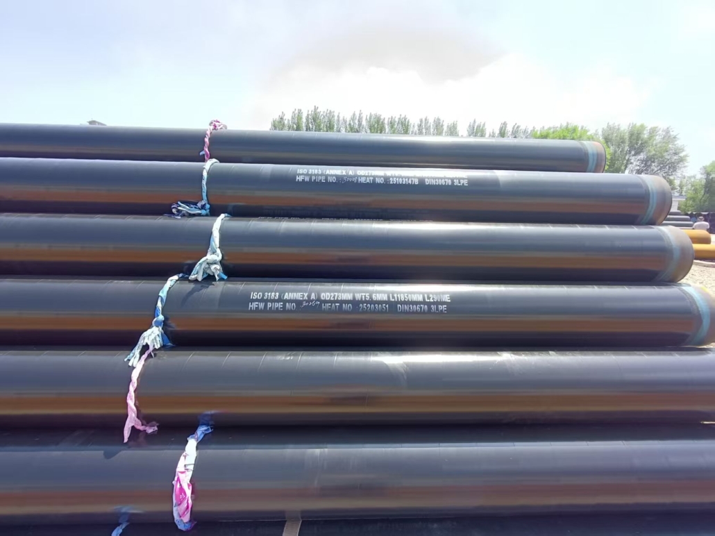
DIN 30670 is the core technical standard for polyethylene anti-corrosion coatings applied to buried steel pipelines for gas and water supply in Germany. The peel strength test for 3PE coatings under this standard focuses on verifying the adhesion between the coating and the substrate as well as interlayer adhesion. All test operations must strictly comply with the standard clauses to eliminate systematic errors and human interference.

Specimen Preparation and Conditioning (Basis for Compliance)

Sampling and Cutting Requirements: Specimens shall be taken from the flat straight sections of finished anti-corrosion pipes, at least 50 mm away from pipe ends, circumferential welds and defective areas. Specimens with coating blisters, pinholes or mechanical damage are strictly prohibited. Specimens shall be prepared by precision mechanical cutting to a standard width of 20 mm ± 0.5 mm, with burr-free and thermally uninjured cuts to prevent pre-delamination between layers caused by cutting stress. A pre-peeled tab of 25 ± 5 mm shall be prepared, only separating the target test interface (FBE/steel substrate, adhesive/FBE, PE/adhesive) without damaging the coating bulk or steel pipe base material.

Specimen Conditioning Specifications: For ambient temperature tests, specimens shall be conditioned in a standard environment of 23 °C ± 2 °C and 50% ± 5% relative humidity for at least 16 h. For elevated temperature peel tests, constant temperature insulation shall be performed at the standard specified temperatures (e.g., 50 °C, 80 °C) for no less than 45 min to ensure the coating reaches full thermal equilibrium; testing shall not commence until the target temperature is achieved.

Specimen Storage Restrictions: Prepared specimens shall be stored in a light-proof and constant-temperature environment. Contact with oil, solvents or direct high-temperature exposure is strictly prohibited to avoid irreversible degradation of coating adhesion properties.

Test Equipment and Parameter Control (Core for Accuracy)

Equipment Calibration and Precision: The tensile testing machine shall meet the Class 1 accuracy requirement of ISO 7500-1, with a legally calibrated force measurement system within the validity period. Special non-metallic anti-slip clamps shall be used with moderate clamping force to prevent crushing of the polyethylene topcoat or specimen slippage.

Constant Parameter Requirements: DIN 30670 specifies a 90° peel mode with a peel angle deviation ≤ ±2°, as angle offset directly leads to distorted data. The peel rate shall be strictly controlled at 100 mm/min ± 5 mm/min, maintaining a constant speed throughout the test without start-stop or speed variation. The data acquisition frequency shall be no less than 10 Hz to fully record the load-displacement curve.

Temperature Control Equipment Requirements: Thermostats for elevated temperature tests shall have a temperature control accuracy ≤ ±1 °C, free from local overheating or temperature fluctuations. Opening the thermostat for specimen adjustment during testing is prohibited to avoid sudden temperature changes affecting test results.

Test Operation and Failure Determination (Key for Validity)

Standard Clamping Operation: Specimens shall be clamped to ensure coaxial alignment of peel force, free from torsion or deflection, with a linear peel path. The first 50 mm and last 20 mm of the peel length are regarded as unstable stress sections; data from these zones shall be discarded, and only load data from the continuous and stable middle peel section shall be collected.

Failure Mode Determination: DIN 30670 defines interfacial adhesive failure as the valid failure mode. Test results shall be invalidated and retesting required if cohesive fracture of the coating, premature peeling caused by specimen cutting damage, clamp slippage or substrate deformation occurs during testing. The type of failure interface shall be accurately recorded, and peel performance of different interfaces shall be tested and documented in separate groups.

Parallel Specimen Control: Each test group shall contain no less than 5 parallel specimens. Outlier data with a dispersion coefficient > 15% shall be excluded, and the arithmetic mean of remaining valid specimens shall be taken as the final result.

Data Calculation and Record Traceability (Guarantee for Compliance)

Data Calculation Criteria: Peel strength is reported in N/mm, calculated as the load per unit width based on the actual specimen width. Conformity shall be determined against the temperature-specified limits in DIN 30670: the measured value of a single specimen shall not be lower than 80% of the standard lower limit, and the group average shall meet the standard index requirements.

Traceable Recording Requirements: The test report shall fully state the DIN 30670 standard revision, specimen number, equipment calibration number, ambient temperature and humidity, insulation duration, peel angle/speed, failure mode, raw load data and curves. Test specimens shall be retained until report issuance for re-inspection and traceability.
DIN 30670 is the core technical standard for polyethylene anti-corrosion coatings applied to buried steel pipelines for gas and water supply in Germany. The peel strength test for 3PE coatings under this standard focuses on verifying the adhesion between the coating and the substrate as well as interlayer adhesion. All test operations must strictly comply with the standard clauses to eliminate systematic errors and human interference.

Specimen Preparation and Conditioning (Basis for Compliance)

Sampling and Cutting Requirements: Specimens shall be taken from the flat straight sections of finished anti-corrosion pipes, at least 50 mm away from pipe ends, circumferential welds and defective areas. Specimens with coating blisters, pinholes or mechanical damage are strictly prohibited. Specimens shall be prepared by precision mechanical cutting to a standard width of 20 mm ± 0.5 mm, with burr-free and thermally uninjured cuts to prevent pre-delamination between layers caused by cutting stress. A pre-peeled tab of 25 ± 5 mm shall be prepared, only separating the target test interface (FBE/steel substrate, adhesive/FBE, PE/adhesive) without damaging the coating bulk or steel pipe base material.

Specimen Conditioning Specifications: For ambient temperature tests, specimens shall be conditioned in a standard environment of 23 °C ± 2 °C and 50% ± 5% relative humidity for at least 16 h. For elevated temperature peel tests, constant temperature insulation shall be performed at the standard specified temperatures (e.g., 50 °C, 80 °C) for no less than 45 min to ensure the coating reaches full thermal equilibrium; testing shall not commence until the target temperature is achieved.

Specimen Storage Restrictions: Prepared specimens shall be stored in a light-proof and constant-temperature environment. Contact with oil, solvents or direct high-temperature exposure is strictly prohibited to avoid irreversible degradation of coating adhesion properties.

Test Equipment and Parameter Control (Core for Accuracy)

Equipment Calibration and Precision: The tensile testing machine shall meet the Class 1 accuracy requirement of ISO 7500-1, with a legally calibrated force measurement system within the validity period. Special non-metallic anti-slip clamps shall be used with moderate clamping force to prevent crushing of the polyethylene topcoat or specimen slippage.

Constant Parameter Requirements: DIN 30670 specifies a 90° peel mode with a peel angle deviation ≤ ±2°, as angle offset directly leads to distorted data. The peel rate shall be strictly controlled at 100 mm/min ± 5 mm/min, maintaining a constant speed throughout the test without start-stop or speed variation. The data acquisition frequency shall be no less than 10 Hz to fully record the load-displacement curve.

Temperature Control Equipment Requirements: Thermostats for elevated temperature tests shall have a temperature control accuracy ≤ ±1 °C, free from local overheating or temperature fluctuations. Opening the thermostat for specimen adjustment during testing is prohibited to avoid sudden temperature changes affecting test results.

Test Operation and Failure Determination (Key for Validity)

Standard Clamping Operation: Specimens shall be clamped to ensure coaxial alignment of peel force, free from torsion or deflection, with a linear peel path. The first 50 mm and last 20 mm of the peel length are regarded as unstable stress sections; data from these zones shall be discarded, and only load data from the continuous and stable middle peel section shall be collected.

Failure Mode Determination: DIN 30670 defines interfacial adhesive failure as the valid failure mode. Test results shall be invalidated and retesting required if cohesive fracture of the coating, premature peeling caused by specimen cutting damage, clamp slippage or substrate deformation occurs during testing. The type of failure interface shall be accurately recorded, and peel performance of different interfaces shall be tested and documented in separate groups.

Parallel Specimen Control: Each test group shall contain no less than 5 parallel specimens. Outlier data with a dispersion coefficient > 15% shall be excluded, and the arithmetic mean of remaining valid specimens shall be taken as the final result.

Data Calculation and Record Traceability (Guarantee for Compliance)

Data Calculation Criteria: Peel strength is reported in N/mm, calculated as the load per unit width based on the actual specimen width. Conformity shall be determined against the temperature-specified limits in DIN 30670: the measured value of a single specimen shall not be lower than 80% of the standard lower limit, and the group average shall meet the standard index requirements.

Traceable Recording Requirements: The test report shall fully state the DIN 30670 standard revision, specimen number, equipment calibration number, ambient temperature and humidity, insulation duration, peel angle/speed, failure mode, raw load data and curves. Test specimens shall be retained until report issuance for re-inspection and traceability.

Standards And Applications of Food-Grade FBE

Food-grade FBE is a food-contact epoxy powder coating that is electrostatically sprayed at room temperature and fused/cured at high temperatures (above 180°C). It features non-toxicity, corrosion resistance, a smooth and easy-to-clean surface, and resistance to microbial growth. Widely used in industries with strict hygiene requirements such as food, beverage, and pharmaceutical manufacturing, it provides reliable protection for equipment and pipelines while ensuring food safety.

Core Standard Systems

Food-grade FBE must comply with both basic safety standards and coating-specific standards, and obtain authoritative certifications to be used in food-contact scenarios.

Chinese National Standards
Standard NumberStandard NameCore Requirements
GB 4806.1-2016National Food Safety Standard – General Safety Requirements for Food Contact Materials and ArticlesSensory requirements (no peculiar odor, no discoloration), migration limits (total migration ≤ 10mg/dm²), heavy metal limits (lead ≤ 0.01mg/kg, cadmium ≤ 0.002mg/kg)
GB 4806.10-2025 (Upcoming Implementation)National Food Safety Standard – Coatings and Coatings for Food Contact UseReplaces the current GB 4806.10-2016, implements hierarchical control based on food contact categories (Category I – direct contact with liquid food, Category II – contact with solid food), and strengthens raw material access and full-process control
GB/T 18593-2010Corrosion Protection Coating of Fusion Bonded Epoxy Powder CoatingsSpecifies physical performance requirements for FBE coatings, such as thickness (generally 150-300μm), adhesion (cross-cut test ≥ Grade 1), and degree of curing (≥ 95%)
GB 31604.1-2021National Food Safety Standard – General Principles for Migration Tests of Food Contact Materials and ArticlesRegulates the selection of food simulants (3% acetic acid for aqueous foods, isooctane for oily foods), temperature (≤ 120°C), and time conditions for migration tests
International Authoritative Standards/Certifications
Standard/CertificationIssuing AuthorityCore Requirements
FDA 21 CFR 177.300U.S. Food and Drug Administration (FDA)Specifically for polymer coatings on metal and electroplated products (including epoxy resins), requiring no release of substances hazardous to health or affecting food sensory properties. Applicable to inner walls of food processing machinery, conveyor belt coatings, etc.
NSF/ANSI 61National Sanitation Foundation (NSF)Certification for drinking water system components, requiring no migration of harmful substances to ensure drinking water safety. Food-grade FBE must pass this certification for use in drinking water transmission pipelines.
NSF/ANSI 51National Sanitation Foundation (NSF)Certification for food equipment materials, requiring compliance with food hygiene requirements and resistance to microbial growth. Applicable to FBE coatings for food processing equipment.
Industry-Specific Standards

CJ/T 120-2016: Technical Specification for Fusion Bonded Epoxy Powder Coatings on Inner Walls of Steel Pipes for Urban Water Supply (applicable to drinking water distribution pipelines)

AWWA C213: American Water Works Association Standard (specifies application requirements for FBE coatings in drinking water pipelines)

CSA Z245.20: Canadian Standards Association Standard (provides detailed guidelines for FBE application and testing)

Key Technical Requirements

In addition to safety standards, food-grade FBE must meet the following technical indicators:

Technical IndicatorRequired ValueTest MethodSignificance
Spessore del rivestimento150-300μmMagnetic Thickness GaugeEnsure sufficient corrosion resistance and mechanical strength
Adhesion≥ Grade 1 (Cross-Cut Test)GB/T 9286 (equivalent to ISO 2409)Prevent coating detachment and food contamination
Degree of Curing≥ 95%Differential Scanning Calorimetry (DSC)Ensure chemical stability of the coating and prevent migration of uncured components
Surface RoughnessRa ≤ 1.6μmSurface Roughness TesterSmooth surface facilitates cleaning and reduces microbial growth
Chemical ResistanceResistant to acids, alkalis (pH 2-12), and food processing cleanersImmersion TestAdapt to chemical corrosion in food processing environments
Hygienic PerformanceComplies with GB 4789.2-2016 (no pathogenic bacteria)Microbial Culture TestEnsure food contact safety
Main Application Scenarios

With its properties of non-toxicity, corrosion resistance, and easy cleaning, food-grade FBE is widely used in the food industry:

Food Processing Industry

Transmission Pipelines: Used for transporting liquid foods such as fruit juice, milk, beer, and sauces. Prevents pipeline corrosion and food contamination, while the smooth surface reduces food residue and microbial growth.

Processing Equipment: Coatings for inner walls of food processing machinery, reactors, storage tanks, and conveyor belts. Resists acid-base corrosion and high-temperature cleaning in food processing environments.

Packaging Equipment: Coatings for can and beverage can production lines, ensuring food hygiene and safety during the packaging process.

Beverage and Drinking Water Industry

Drinking Water Pipelines: Urban tap water and direct drinking water transmission pipelines. Certified by NSF/ANSI 61 to ensure safe and odor-free drinking water.

Beverage Production Lines: Coatings for pipelines and equipment in carbonated drinks, tea drinks, and bottled water production lines. Resists corrosion from carbon dioxide and acidic beverages.

Pharmaceutical and Health Product Industry

Pharmaceutical Water Systems: Purified water and water for injection transmission pipelines. Complies with GMP requirements, preventing microbial contamination and adsorption of pharmaceutical ingredients.

Health Product Production Equipment: Pipelines and reaction equipment for nutrient oral liquids and health product raw materials, ensuring product purity and hygienic safety.

Other Applications

Food-Grade Valves and Fittings: Connectors such as valves, flanges, and elbows used in food and beverage production lines. Prevents corrosion and leakage at connection points.

Food-Grade Storage Tanks: Inner wall coatings for storage tanks used to store food raw materials, semi-finished products, and finished products. Extends tank service life and ensures food quality.

Core Advantages of Food-Grade FBE

Food Safety Assurance: Certified by authoritative bodies such as FDA and NSF, with no migration of harmful substances, complying with food contact material safety requirements.

Excellent Corrosion Resistance: Resists acids, alkalis, salt spray, and corrosion from food processing chemicals, extending equipment service life.

Hygienic and Easy to Clean: The smooth surface (Ra ≤ 1.6μm) reduces food residue and microbial growth, facilitating CIP (Clean-in-Place) and SIP (Sterilize-in-Place).

High Mechanical Strength: Strong adhesion to metal substrates, impact resistance, and wear resistance, adapting to mechanical stress in food processing environments.

Environmental Sustainability: Powder coatings have no solvent emissions, complying with environmental requirements. With a long service life, they reduce waste generation.

Key Points for Compliant Use

Certification Selection: Choose appropriate certifications based on application scenarios (NSF/ANSI 51 for food equipment, NSF/ANSI 61 for drinking water systems, FDA 21 CFR 177.300 for exports to the U.S.).

Coating Thickness Control: Ensure coating thickness is within the 150-300μm range. Too thin a coating affects corrosion resistance, while too thick a coating may cause cracks.

Curing Quality Assurance: Curing temperature must reach above 180°C with a curing degree of ≥ 95% to avoid migration of uncured components into food.

Regular Inspection and Maintenance: Periodically check coating integrity and repair damages promptly to prevent exposure and corrosion of metal substrates.

Core Standard Systems

Food-grade FBE must comply with both basic safety standards and coating-specific standards, and obtain authoritative certifications to be used in food-contact scenarios.

Chinese National Standards

Standard NumberStandard NameCore Requirements
GB 4806.1-2016National Food Safety Standard – General Safety Requirements for Food Contact Materials and ArticlesSensory requirements (no peculiar odor, no discoloration), migration limits (total migration ≤ 10mg/dm²), heavy metal limits (lead ≤ 0.01mg/kg, cadmium ≤ 0.002mg/kg)
GB 4806.10-2025 (Upcoming Implementation)National Food Safety Standard – Coatings and Coatings for Food Contact UseReplaces the current GB 4806.10-2016, implements hierarchical control based on food contact categories (Category I – direct contact with liquid food, Category II – contact with solid food), and strengthens raw material access and full-process control
GB/T 18593-2010Corrosion Protection Coating of Fusion Bonded Epoxy Powder CoatingsSpecifies physical performance requirements for FBE coatings, such as thickness (generally 150-300μm), adhesion (cross-cut test ≥ Grade 1), and degree of curing (≥ 95%)
GB 31604.1-2021National Food Safety Standard – General Principles for Migration Tests of Food Contact Materials and ArticlesRegulates the selection of food simulants (3% acetic acid for aqueous foods, isooctane for oily foods), temperature (≤ 120°C), and time conditions for migration tests
International Authoritative Standards/Certifications
Standard/CertificationIssuing AuthorityCore Requirements
FDA 21 CFR 177.300U.S. Food and Drug Administration (FDA)Specifically for polymer coatings on metal and electroplated products (including epoxy resins), requiring no release of substances hazardous to health or affecting food sensory properties. Applicable to inner walls of food processing machinery, conveyor belt coatings, etc.
NSF/ANSI 61National Sanitation Foundation (NSF)Certification for drinking water system components, requiring no migration of harmful substances to ensure drinking water safety. Food-grade FBE must pass this certification for use in drinking water transmission pipelines.
NSF/ANSI 51National Sanitation Foundation (NSF)Certification for food equipment materials, requiring compliance with food hygiene requirements and resistance to microbial growth. Applicable to FBE coatings for food processing equipment.
Industry-Specific Standards

CJ/T 120-2016: Technical Specification for Fusion Bonded Epoxy Powder Coatings on Inner Walls of Steel Pipes for Urban Water Supply (applicable to drinking water distribution pipelines)

AWWA C213: American Water Works Association Standard (specifies application requirements for FBE coatings in drinking water pipelines)

CSA Z245.20: Canadian Standards Association Standard (provides detailed guidelines for FBE application and testing)

Key Technical Requirements

In addition to safety standards, food-grade FBE must meet the following technical indicators:

Technical IndicatorRequired ValueTest MethodSignificance
Spessore del rivestimento150-300μmMagnetic Thickness GaugeEnsure sufficient corrosion resistance and mechanical strength
Adhesion≥ Grade 1 (Cross-Cut Test)GB/T 9286 (equivalent to ISO 2409)Prevent coating detachment and food contamination
Degree of Curing≥ 95%Differential Scanning Calorimetry (DSC)Ensure chemical stability of the coating and prevent migration of uncured components
Surface RoughnessRa ≤ 1.6μmSurface Roughness TesterSmooth surface facilitates cleaning and reduces microbial growth
Chemical ResistanceResistant to acids, alkalis (pH 2-12), and food processing cleanersImmersion TestAdapt to chemical corrosion in food processing environments
Hygienic PerformanceComplies with GB 4789.2-2016 (no pathogenic bacteria)Microbial Culture TestEnsure food contact safety
Main Application Scenarios

With its properties of non-toxicity, corrosion resistance, and easy cleaning, food-grade FBE is widely used in the food industry:

Food Processing Industry

Transmission Pipelines: Used for transporting liquid foods such as fruit juice, milk, beer, and sauces. Prevents pipeline corrosion and food contamination, while the smooth surface reduces food residue and microbial growth.

Processing Equipment: Coatings for inner walls of food processing machinery, reactors, storage tanks, and conveyor belts. Resists acid-base corrosion and high-temperature cleaning in food processing environments.

Packaging Equipment: Coatings for can and beverage can production lines, ensuring food hygiene and safety during the packaging process.

Beverage and Drinking Water Industry

Drinking Water Pipelines: Urban tap water and direct drinking water transmission pipelines. Certified by NSF/ANSI 61 to ensure safe and odor-free drinking water.

Beverage Production Lines: Coatings for pipelines and equipment in carbonated drinks, tea drinks, and bottled water production lines. Resists corrosion from carbon dioxide and acidic beverages.

Pharmaceutical and Health Product Industry

Pharmaceutical Water Systems: Purified water and water for injection transmission pipelines. Complies with GMP requirements, preventing microbial contamination and adsorption of pharmaceutical ingredients.

Health Product Production Equipment: Pipelines and reaction equipment for nutrient oral liquids and health product raw materials, ensuring product purity and hygienic safety.

Other Applications

Food-Grade Valves and Fittings: Connectors such as valves, flanges, and elbows used in food and beverage production lines. Prevents corrosion and leakage at connection points.

Food-Grade Storage Tanks: Inner wall coatings for storage tanks used to store food raw materials, semi-finished products, and finished products. Extends tank service life and ensures food quality.

Core Advantages of Food-Grade FBE

Food Safety Assurance: Certified by authoritative bodies such as FDA and NSF, with no migration of harmful substances, complying with food contact material safety requirements.

Excellent Corrosion Resistance: Resists acids, alkalis, salt spray, and corrosion from food processing chemicals, extending equipment service life.

Hygienic and Easy to Clean: The smooth surface (Ra ≤ 1.6μm) reduces food residue and microbial growth, facilitating CIP (Clean-in-Place) and SIP (Sterilize-in-Place).

High Mechanical Strength: Strong adhesion to metal substrates, impact resistance, and wear resistance, adapting to mechanical stress in food processing environments.

Environmental Sustainability: Powder coatings have no solvent emissions, complying with environmental requirements. With a long service life, they reduce waste generation.

Key Points for Compliant Use

Certification Selection: Choose appropriate certifications based on application scenarios (NSF/ANSI 51 for food equipment, NSF/ANSI 61 for drinking water systems, FDA 21 CFR 177.300 for exports to the U.S.).

Coating Thickness Control: Ensure coating thickness is within the 150-300μm range. Too thin a coating affects corrosion resistance, while too thick a coating may cause cracks.

Curing Quality Assurance: Curing temperature must reach above 180°C with a curing degree of ≥ 95% to avoid migration of uncured components into food.

Regular Inspection and Maintenance: Periodically check coating integrity and repair damages promptly to prevent exposure and corrosion of metal substrates.

Comprehensive Analysis Of Applications And Standards For FBE Steel Pipes With Different Thicknesses

1. Core Classification and Technical Characteristics of FBE Coating Thickness

FBE coatings are categorized into three types based on thickness: Single-Layer Basic Type, Single-Layer Reinforced Type, and Dual-Layer Composite Type, with their performance increasing in a stepped manner as thickness increases:

Coating TypeThickness RangeCore CharacteristicsProcess Features
Single-Layer Basic300-400 μmAdhesion strength ≥ 5 MPa, salt spray resistance ≥ 3000 hoursSingle electrostatic spraying, room-temperature curing
Single-Layer Reinforced400-500 μm40% higher impact resistance, excellent cathodic disbondment performanceThickened spraying + high-temperature curing (230℃)
Dual-Layer Composite≥ 620 μm (base + top)Strong adhesion of base layer, wear/chemical corrosion resistance of top layerDouble spraying, layered functional design

2. Precise Matching of Application Scenarios by Thickness

1. Single-Layer Basic Type (300-400 μm): Conventional Corrosion Environments

  • Typical Scenarios:
    • Municipal water transmission pipelines (DN ≤ 250 mm, soil resistivity ≥ 100 Ω·m)
    • Underground coal mine gas extraction pipes (pressure ≤ 1.6 MPa)
    • Thermal power plant circulating water pipelines (water temperature ≤ 60℃)
  • Case Reference: The gathering and transportation pipeline network of Tarim Oilfield adopts ASTM A53 Gr.B steel pipes with 350 μm FBE coating, achieving a 98.7% coating integrity rate after 5 years.

2. Single-Layer Reinforced Type (400-500 μm): Moderately Severe Environments

  • Typical Scenarios:
    • Acid-alkali waste liquid transmission in chemical industrial parks (pH 3-11)
    • Buried gas pipelines in coastal areas (soil salt content ≤ 3%)
    • Trenchless crossing pipelines under highways (anti-rolling requirements)
  • Suitable Pipe Diameters: DN 250-DN 800. According to SY/T 0315, coating thickness increases with pipe diameter (e.g., ≥ 450 μm for DN 800).

3. Dual-Layer Composite Type (≥ 620 μm): Extreme Service Environments

  • Typical Scenarios:
    • Submarine oil transmission pipelines (water depth ≤ 50 m, seawater immersion resistance)
    • High-temperature steam pipelines (temperature ≤ 120℃, thermal aging resistance)
    • Buried pipelines in rocky areas (gravel scratch resistance)
  • Standard Requirement: Complies with the “Extra Reinforced Class” specification in DIN 30671, with top layer thickness ≥ 400 μm.

4. FBE Base Layer in Composite Structures (120-200 μm)

  • Application Form: Serves as the bonding base layer for 3PE/3PP coatings
  • Scenario Adaptation: Long-distance oil and gas transmission pipelines (DN ≥ 500 mm)
  • Thickness Specification: GB/T 23257 requires the FBE base layer to be ≥ 120 μm for pipes with DN ≤ 100 mm, and ≥ 180 μm for pipes with DN ≥ 800 mm.

3. Core Domestic and International Standards & Thickness Regulations

1. Chinese Standards

Standard NumberApplication ScenarioThickness Requirement
SY/T 0315-2005FBE Coatings for Buried Steel PipelinesSingle layer ≥ 300 μm, dual layer ≥ 620 μm
GB/T 23257-2022FBE for PE Anticorrosive LayersBase layer ≥ 120 μm; total thickness graded by pipe diameter (1.8-3.7 mm)
CJ/T 120-2008Municipal Water Supply PipelinesSingle layer ≥ 350 μm, adhesion strength ≥ 3 MPa

2. International Standards

  • DIN 30671 (Germany):
    • Normal Class: 300-400 μm (buried in soil)
    • Reinforced Class: ≥ 500 μm (underwater or rocky areas)
  • AWWA C210 (USA):
    • Drinking water pipelines: Single layer ≥ 300 μm, no heavy metal leaching
  • ISO 21809-1 (International):
    • Dual-Layer FBE: Base layer 120-150 μm, top layer ≥ 500 μm

4. Key Considerations for Selection

  1. Corrosion Grade Matching:
    • Mild corrosion (soil resistivity > 500 Ω·m): Select 300-400 μm single-layer coating
    • Severe corrosion (salt marshes/chemical industrial zones): Mandatory use of ≥ 620 μm dual-layer coating
  2. Pipe Diameter Correlation Principle:
    • DN ≤ 100 mm: Minimum thickness 300 μm (to avoid brittleness and cracking caused by excessive coating thickness)
    • DN ≥ 800 mm: Reinforced class ≥ 450 μm (to resist greater external pressure)
  3. Core Acceptance Indicators:
    • Thickness Uniformity: Deviation ≤ ±50 μm for the same pipe section (per SY/T 0315)
    • Cathodic Disbondment: Immersion at 70℃ for 30 days, disbondment width ≤ 10 mm

Operating Temperature Of FBE Steel Pipes

FBE steel pipes refer to Fusion Bonded Epoxy Coated Steel Pipes. Their operating temperature mainly depends on the heat resistance of the FBE coating, with the core applicable temperature range and influencing factors as follows:

I. Core Operating Temperature Range

According to industry standards for FBE coatings (e.g., GB/T 23257-2017 Polyethylene Anticorrosive Coatings for Buried Steel Pipes, and anticorrosion requirements supporting API 5L Specification for Line Pipe), the operating temperature is divided into long-term use e short-term use:

  • Long-term operating temperature: Generally -30℃ ~ 80℃

Within this temperature range, the FBE coating can maintain stable adhesion, impact resistance, and corrosion resistance, without cracking, peeling, or accelerated aging due to temperature changes (suitable for long-term stable working conditions such as buried water transportation, gas transmission, and ordinary chemical fluid transportation).

  • Short-term operating temperature: Maximum tolerance up to 120℃ (duration ≤ 1 hour)

This is only applicable to temporary working conditions (e.g., pipeline hydrostatic testing, short-term transportation of slightly high-temperature media). Exceeding 120℃ or long-term exposure to environments above 80℃ will cause the coating to soften, decrease in strength, and even lead to thermal aging failure.

II. Key Factors Affecting Operating Temperature

  1. FBE Coating Formulation
    1. General-purpose FBE: The upper heat resistance limit is 80℃, suitable for normal-temperature media;
    1. High-temperature resistant FBE (modified grade): By adding heat-resistant resins (e.g., phenol-modified epoxy), the long-term operating temperature can be increased to 100℃ ~ 120℃ (suitable for working conditions such as hot oil and high-temperature sewage, requiring customized production separately).
  2. Coating Curing Quality

Insufficient curing of the FBE coating (e.g., insufficient curing temperature or too short curing time) will result in low coating crosslinking density, significantly reduced heat resistance, and potential blistering or peeling even at 60℃ ~ 70℃.

  • Medium Environment

If the transported medium contains strongly corrosive substances (e.g., strong acids, strong alkalis, organic solvents), high temperatures will accelerate the chemical reaction between the medium and the coating. In such cases, the actual operating temperature should be reduced (e.g., using at normal temperature) to avoid premature coating failure.

III. Temperature Requirements for Typical Application Scenarios

Application ScenarioRecommended Operating TemperatureNotes
Buried natural gas/petroleum transmission pipelines-20℃ ~ 70℃Avoid local overheating of the pipe body caused by direct sunlight exposure
Municipal tap water/sewage pipelines0℃ ~ 60℃Prevent frost heaving at low temperatures and avoid microbial growth at high temperatures
Ordinary chemical fluid pipelines-10℃ ~ 80℃Adjust according to the corrosiveness of the medium; reduce to normal temperature for strongly corrosive media
Temporary pressure testing/maintenance conditions≤120℃ (short-term)Single duration should not exceed 1 hour; avoid frequent over-temperature

IV. Precautions

  1. Prohibition of over-temperature use: Long-term exposure above 80℃ (for general-purpose FBE) or 120℃ (for high-temperature resistant FBE) will cause thermal aging of the coating and loss of adhesion, eventually leading to pipe rust;
  2. Low-temperature limitation: Below -30℃, the FBE coating will become brittle and its impact resistance will decrease. Avoid external impact on the pipeline (e.g., provide cushioning protection during burial);
  3. Selection matching: If the operating temperature exceeds 80℃, clearly require suppliers to provide “high-temperature resistant FBE coatings” and submit coating heat resistance test reports (e.g., high-temperature adhesion test, thermal aging test data).

In summary, the conventional operating temperature of FBE steel pipes is mainly -30℃ ~ 80℃. For special working conditions, adaptation can be achieved by customizing high-temperature resistant coatings or adjusting the operating temperature. The core principle is to ensure the coating maintains structural and performance stability throughout its service life.

Transportation And Storage Of FBE-Coated Steel Pipes

The transportation and storage of Fusion-Bonded Epoxy (FBE)-coated steel pipes are critical links in ensuring their corrosion protection performance. Although FBE coatings exhibit excellent corrosion resistance, they are relatively brittle with poor impact and scratch resistance, and are sensitive to ambient temperature, humidity, and mechanical forces. Therefore, standardized transportation and storage management is essential to prevent coating damage, aging, or structural damage to the pipes, thereby ensuring the effectiveness of subsequent construction and long-term operation. Below are the specific operational specifications:

1. Preparation Before Transportation

Before transportation, coating quality verification e protective pre-treatment must be completed to minimize the risk of damage during transportation:

1.1 Coating Quality Re-inspection

  • In accordance with GB/T 39636-2020 Technical Specification for Fusion-Bonded Epoxy Powder External Coatings on Steel Pipes, re-inspect the coating’s appearance (no pinholes, bubbles, or peeling), thickness (single layer ≥ 300μm, double layer ≥ 600μm), and adhesion strength (≥ 10MPa). Non-conforming products must be repaired before transportation.
  • Conduct a comprehensive inspection of coating integrity using a spark tester (15kV voltage) to ensure no leakage points (inspection speed ≤ 0.3m/s).

1.2 Protection of Pipe Ends

  • Fit plastic protective caps (HDPE material, thickness ≥ 3mm) on both ends of the pipes (beveled or flat ends) to prevent foreign objects from entering the pipe interior and avoid collision damage to the coatings at the ends.
  • For flanged pipes, cover the flange sealing surfaces with anti-rust film + rigid protective covers to prevent scratches or rust on the sealing surfaces.

1.3 Selection of Packaging Methods

Choose appropriate packaging based on the pipe specifications (length, diameter), with the core goal of preventing friction and collision between pipes:

Steel Pipe TypePackaging Method
Short pipes (≤ 6m)Bundled with steel strips (strip width ≥ 30mm, ≥ 3 bundling points). Place rubber pads or non-woven fabrics (thickness ≥ 5mm) between each bundle of pipes.
Long pipes (> 6m)Fixed with dedicated frames (steel or wood, with soft liners attached to the inner sides of the frames). The load capacity of a single frame must not exceed the design limit.
Small-diameter pipes (≤ 200mm)Insert into dedicated plastic pipe sleeves (length ≥ 100mm) to avoid direct contact between pipe orifices.

2. Transportation Process Control

During transportation, focus on preventing mechanical impact, friction scratches, and environmental erosion. The specific requirements are as follows:

2.1 Loading and Unloading Specifications

  • Utilizzo specialized lifting equipment exclusively: Prioritize hooks and slings (width ≥ 100mm) with soft liners (rubber or nylon). Direct bundling of pipes with steel wire ropes is prohibited (to avoid indentation damage to the coating).
  • Control the loading/unloading speed at ≤ 0.5m/s. Throwing or impacting is prohibited. Pipes must be kept horizontal when lifted to prevent coating scratches caused by tilting.

2.2 Transportation Vehicles and Fixation

  • Utilizzo flatbed trucks or dedicated tank trucks. The truck bed must be paved with non-slip rubber sheets or wooden pads (thickness ≥ 10mm) to prevent pipe sliding during transportation.
  • Pipe fixation methods:
    • For bundled short pipes: Secure them with steel strips + soft pads (a second round of fixation). Place non-woven fabrics between the steel strips and the coating to avoid direct metal contact.
    • For long pipes in frames: Fix the frames to the truck bed with bolts, and secure the pipes inside the frames with wedges (wooden, with soft liners attached) to prevent displacement due to jolting.

2.3 Environmental Protection Measures

  • Transportation in rainy weather: Pipes must be covered with rainproof tarpaulins (PVC material, thickness ≥ 0.3mm). Ventilation holes (1 hole every 5m, diameter ≥ 50mm) must be reserved on the tarpaulins to prevent condensation accumulation in the truck bed, which could dampen the coating.
  • Transportation in high temperatures (ambient temperature > 35℃): Cover the top of the truck bed with sunshade nets to avoid prolonged exposure of the FBE coating to sunlight (which accelerates coating aging).
  • Transportation in low temperatures (ambient temperature < 0℃): For long-distance transportation (> 24h), provide preheating protection for the coating surface (cover with thermal insulation cotton to prevent coating embrittlement due to low temperatures).

2.4 Transportation Routes and Speed

  • Prioritize smooth highways and avoid bumpy roads (e.g., unpaved roads, potholed sections). Maintain a driving speed ≤ 60km/h (≤ 80km/h on highways). Decelerate gently when turning or braking to prevent pipe impact caused by sudden stops.

3. Storage Management Specifications

The storage of FBE-coated steel pipes must meet the requirements of moisture prevention, pressure prevention, and corrosion prevention. Strictly follow the following standards for storage sites and stacking methods:

3.1 Requirements for Storage Sites

  • The site must have hardened ground (concrete or asphalt, flatness tolerance ≤ 5mm) with a drainage slope ≥ 3‰ to prevent water accumulation from soaking the pipes.
  • Keep away from corrosive environments: Prohibit placement near chemical industrial zones, salt spray areas, or sewage ditches. Set up guardrails around the site to prevent unauthorized mechanical access.
  • Environmental control for the site: The storage temperature should be -5℃ ~ 35℃, with relative humidity ≤ 85%. For long-term storage (> 3 months), build sunshade sheds (top height ≥ 4m) to avoid direct sunlight and rain erosion.

3.2 Stacking Methods and Load Control

  • Bottom support: Use wooden or concrete support blocks (height ≥ 200mm, spacing between supports ≤ 3m). Attach soft liners (rubber, thickness ≥ 10mm) to the top of the support blocks. Direct placement of pipes on the ground is prohibited.
  • Stacking height:
    • For pipes with diameter ≤ 500mm: Maximum stacking height ≤ 5 layers, with rubber pads (thickness ≥ 5mm) placed between each layer.
    • For pipes with diameter > 500mm: Maximum stacking height ≤ 3 layers. Mark the bottom-layer pipes separately to prevent long-term compression deformation.
  • Stacking spacing: Pipes of different specifications and batches must be stored in separate zones with a spacing ≥ 1m between zones. Install identification signs (indicating specifications, production date, and coating type) for easy management.

3.3 Maintenance for Long-Term Storage

  • Regular inspections: Daily check the coating appearance (for scratches or bubbles); weekly inspect whether the support blocks are deformed or the ground is waterlogged; monthly conduct random inspections of coating integrity using a spark tester (sampling ratio ≥ 5%).
  • Environmental regulation: Strengthen ventilation during the rainy season (open the side curtains of the sunshade shed). In winter, if the site temperature < -10℃, provide intermittent preheating for the pipes (use a hot air blower to blow the coating surface, controlling the temperature at 10℃ ~ 15℃ to prevent coating embrittlement).
  • End protection: If the plastic protective caps fall off, replace them immediately to prevent dust and moisture from entering the pipe interior and causing internal rust.

4. Common Issues and Emergency Handling

4.1 Coating Scratches During Transportation

  • For minor scratches (scratch area ≤ 30mm²): Upon arrival at the destination, immediately repair using a special FBE repair agent (two-component liquid epoxy). Follow the process: grinding → cleaning → application → curing. Conduct a spark test after repair.
  • For moderate scratches (scratch area > 30mm²): Mark the location, prohibit use, and contact the manufacturer to send professionals for on-site repair or return the pipes to the factory for handling.

4.2 Coating Blistering During Storage

  • Cause: Mostly due to site humidity and water ingress between the coating and the substrate.
  • Handling: Cut open the blistered area, remove moisture and rust, re-blast the surface (to Sa2.5 standard), apply FBE powder, and test the adhesion strength (≥ 10MPa) after curing.

4.3 Pipe Deformation

  • For slight bending deformation (deformation ≤ L/1000, where L is the pipe length): Straighten slowly using a dedicated straightening machine, and re-inspect the coating integrity after straightening.
  • For severe deformation (deformation > L/1000): Classify as scrapped and prohibit use.

Repair Standards And Methods For FBE Anti-corrosion Steel Pipes

Repair of FBE anti-corrosion steel pipes (Fusion Bonded Epoxy anti-corrosion steel pipes) must comply with strict standards and specifications to ensure that the anti-corrosion performance of the repaired coating matches the original coating and guarantee the long-term operational safety of the pipeline. The following details the repair standards, repair methods, and quality inspection from three aspects:

I. Core Standards for Repair

The repair of FBE anti-corrosion coatings must refer to authoritative domestic and international standards, mainly including:

  1. Domestic Standards
    1. Technical Specification for Fusion Bonded Epoxy Powder External Coating of Steel Pipes (SY/T 0315-2013): Clearly specifies the repair requirements for FBE coating damage, including repair materials, surface treatment, construction processes, and inspection methods.
    2. Technical Specification for Repair of Anti-corrosion Coatings on Buried Steel Pipes (GB/T 5135.22-2019): Provides general regulations on the repair process and quality control of anti-corrosion coatings (including FBE) for buried pipelines.
    3. Code for Construction of Oil and Gas Pipeline Crossing Engineering (GB 50424-2015): Involves special requirements for damage repair of FBE pipelines in crossing sections.
  2. International Standards
    1. ISO 21809-3 Petroleum and Natural Gas Industries – Pipeline Transportation Systems – Part 3: Steel Pipe Coatings: Puts forward internationally accepted requirements for the compatibility of FBE coating repair materials and construction processes.
    2. AWWA C213 Standard for Fusion-Bonded Epoxy Coatings for Steel Water Pipelines: Emphasizes the hygienic safety of materials for the repair of FBE coatings in drinking water pipelines.

II. Premises for Repair and Classification of Damage

Before repair, it is necessary to evaluate the type and extent of damage to determine whether repair is required:

  • Minor damage: Local scratches on the coating (depth ≤ 50% of coating thickness), pinholes (diameter ≤ 1mm).
  • Moderate damage: Local peeling of the coating (area ≤ 100cm²), scratches with depth > 50% of coating thickness but without exposing the substrate (steel pipe not exposed).
  • Severe damage: Large-area peeling of the coating (area > 100cm²), exposure of the substrate (direct exposure of the steel pipe), and steel pipe deformation caused by mechanical damage.

III. Specific Repair Methods

Repair must follow the process of “surface treatment → material selection → coating application”. The repair methods vary slightly according to the degree of damage:

1. Surface Treatment (Core Step)

Regardless of the type of damage, the damaged area and the surrounding 50-100mm range must be surface-treated to ensure the substrate is clean and rough, thereby enhancing the adhesion of repair materials:

  • Rust removal grade: For areas with exposed substrate (steel pipe exposed), the rust removal grade must reach Sa2.5 (near-white rust removal), which can be achieved by sandblasting; for non-substrate-exposed areas (only coating damage), it must reach St3 (thorough manual rust removal), which can be done using wire brushes, sandpaper, or power tools for grinding.
  • Cleanliness requirements: Remove rust, oil, dust, and old coating debris from the surface, clean it with dry compressed air or a lint-free cloth, and ensure the surface moisture content is ≤ 4%.

2. Selection of Repair Materials

Repair materials must be compatible with the original FBE coating (chemical stability and adhesion matching) and meet anti-corrosion performance requirements:

  • Minor damage (pinholes, shallow scratches): Two-component epoxy repair paint (such as solvent-free epoxy coating) is used, with a dry film thickness ≥ 150μm (equivalent to the thickness of the original FBE coating).
  • Moderate damage (local peeling, deep scratches): Modified epoxy repair paste (paste-like, can be thickly applied) or FBE repair powder (requires heat curing, suitable for high-demand scenarios) is used, with a dry film thickness ≥ 200μm.
  • Severe damage (substrate exposure, large-area peeling): First apply an epoxy primer (dry film thickness ≥ 80μm), then apply a repair coating of the same type as the original FBE (such as high-build epoxy coating), with a total dry film thickness ≥ 300μm (not less than the thickness of the original coating).

3. Coating Application

  • Manual application: Suitable for small-area damage (< 100cm²). Use a scraper or brush to evenly apply the repair material to the treated surface, ensuring no bubbles or sagging, and the edges transition smoothly with the original coating (avoiding steps).
  • Heat curing: If FBE repair powder is used, the repair area must be preheated to 180-220℃ (consistent with the curing temperature of the original FBE) using a heat gun or medium-frequency heating equipment, then the powder is sprayed and allowed to cool and cure naturally.
  • Multi-layer application: For areas requiring higher thickness (such as severe damage), 2-3 layers of coating must be applied, with an interval of ≥ 4 hours between each layer (after thorough drying) to avoid cracking caused by excessive thickness of a single layer.

IV. Quality Inspection Standards

After repair, the following inspections must be conducted to ensure qualification:

  1. Appearance: The coating surface is flat, without bubbles, pinholes, or sagging, and connects smoothly with the original coating, with no obvious color difference.
  2. Spessore: Detected with a coating thickness gauge, the dry film thickness is not less than that of the original FBE coating (usually ≥ 300μm), and the local minimum thickness is not less than 80% of the design value.
  3. Adhesion: Using the cross-cut test (grid spacing 1mm, coating peeling ≤ 5% after tape peeling) or the pull-off test (adhesion ≥ 5MPa, consistent with the original coating).
  4. Pinhole detection: Detected with a spark tester (voltage set according to thickness: 15-30kV for 100-300μm), with no breakdown (no sparks).

How To Improve The Service Life Of FBE Anti-corrosion Steel Pipes?

FBE (Fusion Bonded Epoxy) anti-corrosion steel pipes use steel pipes as the matrix, and the epoxy powder is melted and cured on the surface of the steel pipes through high-temperature spraying to form an anti-corrosion layer. To improve the service life of FBE anti-corrosion steel pipes, efforts can be made in multiple links such as production and manufacturing, transportation and storage, installation and use, and later maintenance:

Production and Manufacturing Link

  • Optimize Steel Pipe Pretreatment: The cleanliness and roughness of the steel pipe surface directly affect the adhesion of the FBE coating. Before coating, shot blasting or sandblasting is used to thoroughly remove impurities such as rust, oil stains, and oxide scales on the steel pipe surface, so that the steel pipe surface reaches Sa2.5 level (near-white level), and the roughness is controlled at 40 – 100μm. Appropriate roughness can increase the contact area between the coating and the steel pipe, enhance adhesion, reduce the risk of coating peeling, and prolong the service life.
  • Strictly Control the Coating Process: Precisely control the spraying temperature, thickness, and curing time of the epoxy powder. Generally, the spraying temperature is 230 – 250℃, the coating thickness is controlled at 300 – 500μm according to the requirements of the use environment, and the curing time needs to ensure that the powder is completely melted and cross-linked and cured. A stable coating process can ensure that the coating is uniform, dense, and free of defects such as pinholes and bubbles, effectively blocking the intrusion of corrosive media.
  • Select High-Quality Raw Materials: Select reliable-quality epoxy powder to ensure that it has good chemical corrosion resistance, water resistance, weather resistance, and mechanical properties. High-quality epoxy powder can maintain stable anti-corrosion performance for a long time in different environments. At the same time, the quality of the steel pipe itself is also crucial. Select steel pipes that meet relevant standards, have uniform wall thickness, and excellent material quality to reduce corrosion problems caused by defects of the steel pipes themselves.

Transportation and Storage Link

  • Strengthen Protective Packaging: During transportation, use appropriate packaging materials for FBE anti-corrosion steel pipes, such as wrapping with plastic film or protective sleeves specially for anti-corrosion pipes, to prevent damage to the coating due to collision and friction between steel pipes. For long-distance transportation, soft pads should be laid at the bottom of the carriage, and the steel pipes should be fixed to avoid coating damage caused by transportation bumps.
  • Reasonably Plan Storage: The storage site should be a dry and well-ventilated place to avoid the steel pipes being in a humid environment for a long time. The steel pipes should be stored elevated, keeping a certain distance from the ground to prevent the coating from being eroded by ground moisture. At the same time, direct sunlight should be avoided to prevent the coating from aging due to ultraviolet radiation and shortening the service life.

Installation and Use Link

  • Standardize Installation Operations: During the installation process, strictly follow the operating procedures, avoid pulling and bending the steel pipes with force, and prevent the coating from cracking or peeling due to excessive force. Use appropriate connection methods. For example, when welding, protective measures should be taken to prevent welding spatter from damaging the coating. For coating damage caused during the installation process, it should be repaired in a timely manner to ensure the integrity of the anti-corrosion layer.
  • Control the Use Environment: Try to avoid using FBE anti-corrosion steel pipes in harsh environments such as extreme temperatures, high humidity, and strong acids and alkalis. If unavoidable, additional protective measures can be taken, such as adding an insulating layer and a protective sleeve outside the pipeline, to reduce the erosion of the environment on the coating. At the same time, parameters such as the temperature, 酸碱度 (acidity and alkalinity), and flow rate of the conveying medium should be controlled to reduce the corrosion effect of the medium on the steel pipes and the coating.

Later Maintenance Link

  • Regular Detection and Evaluation: Establish a regular detection system, and use technical means such as ultrasonic detection and leak point detection to check the integrity, adhesion of the FBE coating, and the corrosion of the steel pipes. Through regular detection, potential problems can be found in a timely manner, and corresponding repair measures can be taken to prevent the problems from expanding.
  • Timely Repair the Coating: Once problems such as coating damage and aging are found, the coating should be repaired in a timely manner. According to the degree of coating damage, select an appropriate repair method. For example, for small-area damage, manual brushing or spraying of epoxy repair paint can be used; for large-area damage, re-FBE coating treatment is required.

Inspection Standards for FBE Anticorrosive Coatings

FBE (Fusion-Bonded Epoxy) anticorrosive coating inspection standards encompass international, national, and industry specifications, focusing primarily on coating performance parameters and acceptance requirements. Below is a detailed overview of the core standard systems and key technical indicators:

I. International Standard System

  1. ISO 21809 Series
    1. ISO 21809-1:2018: Specifies that the FBE primer layer thickness in 3-layer polyethylene (3LPE)/polypropylene (3LPP) coatings shall be ≥300μm, with adhesion ≥5MPa.
    1. ISO 21809-11:2019: Requires field joint and repair coatings to match the original coating thickness and pass the cathodic disbondment test (65°C, 28 days) with a disbondment distance ≤10mm .
    1. ISO 12944-6: Salt spray testing (ISO 9227) mandates that FBE coatings withstand 1,000 hours of testing without blistering or rusting .
  2. ASTM Standards
    1. ASTM D4541-22: Adhesion testing requires a pull-off strength ≥5MPa and a loading rate of 0.8MPa/s ±10% .
    1. ASTM G42-11: High-temperature cathodic disbondment testing (80°C, 0.5MPa) allows a maximum disbondment distance of ≤15mm .
    1. ASTM A 775/A 775M: General standard for epoxy coatings, specifying requirements for coating thickness, adhesion, and continuity.
  3. NACE SP0169-2024
    1. Coating insulation resistance ≥10,000Ω·m², with a cathodic protection potential ≤-0.85V (vs CSE) .

II. Chinese National Standards

  1. GB/T 39636-2020 (Core Standard)
    1. Spessore: Single-layer FBE: 350μm ±50μm; double-layer FBE: total thickness ≥600μm, with local minimum thickness ≥80% of the design value.
    1. Adhesion: Pull-off strength ≥5MPa; cross-cut method grade ≥2 (GB/T 9286-2021) .
    1. Cathodic Disbondment: Disbondment distance ≤15mm after testing at 65°C for 28 days .
  2. GB/T 4956-2003
    1. Thickness measurement accuracy for magnetic substrates: ±10μm, with at least 3 measurements per square meter .
  3. GB/T 5210-2006
    1. Pull-off test requires a specimen diameter of 20mm ±0.5mm and surface preparation to Sa2.5 grade.

III. Industry Standards

  1. SY/T 4113.11-2023 (Replacing SY/T 0063-1999)
    1. Holiday Detection: High-voltage spark testing voltage calculated as  V = 7900\sqrt{T}  (T = thickness in mm), with a typical value of 2.1kV (0.4mm thickness) and a holiday density ≤2 defects/m² .
    1. Low-Voltage Detection: DC voltage ≤100V, used to detect thickness deficiencies .
  2. SY/T 0315-97
    1. Double-layer FBE total thickness ≥600μm, requiring passage of a 1.5J impact test and 3° bend test without disbondment .
  3. SY/T 7036-2016
    1. Compatibility requirements for coatings and cathodic protection in oil and gas station pipelines: current density ≤10μA/cm² .

IV. Special Scenario Standard Requirements

  1. High-Temperature Environments
    1. Hot oil pipelines must pass the ASTM G42 test (80°C, 0.5MPa) with a disbondment distance ≤15mm .
    1. Glass transition temperature (Tg) must exceed 80°C, verified via DSC testing.
  2. Buried Pipelines
    1. Coating insulation resistance ≥10,000Ω·m², with a cathodic protection potential ≤-0.85V (vs CSE).
    1. Combined with Close Interval Potential Survey (CIPS) to assess defect distribution.
  3. Repair Projects
    1. Repaired areas must meet thickness, adhesion, and holiday detection requirements, with interface bond strength ≥4MPa.

V. Surface Preparation and Calibration Specifications

  1. Surface Preparation Standards
    1. Sandblasting cleanliness grade must reach Sa2.5 (GB/T 8923.1) or SSPC-SP 10 (near-white grade).
  2. Equipment Calibration
    1. Thickness Gauges: Calibrated using standard test blocks (e.g., 350μm ±5μm), with an error ≤±5%.
    1. Spark Testers: Verified daily using calibration plates with artificial defects, ensuring voltage error ≤±2%.
  3. Reporting Requirements
    1. Test data must include location, equipment model, calibration records, and bear CMA/CNAS accreditation stamps.

Through this standard system, the thickness, adhesion, corrosion resistance, and compatibility with cathodic protection of FBE anticorrosive coatings can be comprehensively evaluated, ensuring long-term reliability in oil & gas, chemical, and other industrial applications.

Heat Treatment Defects Of Steel Pipes And Their Prevention

During the heat treatment process of steel pipes, various defects may occur due to improper process parameters, equipment failures, or operational errors. The following is a detailed analysis of common defects and their preventive measures:

I. Defects in the Heating Stage

  1. Oxidation and Decarburization
    Defect manifestation: An oxide scale (Fe₃O₄, Fe₂O₃) forms on the surface of the steel pipe, and the loss of carbon elements leads to a decrease in surface hardness.
    Cause: Excessive air (oxidizing atmospheres such as O₂, H₂O, etc.) in the heating furnace, too high a heating temperature, or too long a holding time.
    Preventive measures:
    Use a controlled atmosphere furnace (such as N₂, Ar protective gas, or drip methanol and acetone to generate a protective atmosphere).
    Coat the surface of the workpiece with an anti-oxidation coating (such as a borax coating).
    Strictly control the heating temperature and time to avoid overheating.
  2. Coarse Grain (Overheating)
    Defect manifestation: The austenite grains grow excessively, resulting in a decrease in mechanical properties (reduction in toughness and plasticity).
    Cause: The heating temperature exceeds the critical temperature by a large margin (for example, overheating occurs when the quenching heating temperature is 50~80℃ higher than the Ac3 line), or the holding time is too long.
    Preventive measures:
    Accurately set the heating temperature (according to the process specifications of the steel grade, for example, the quenching temperature of 45 steel is 840±10℃).
    Adopt stepwise heating or rapid heating technology to reduce the residence time at high temperatures.
    For overheated workpieces, they can be reprocessed through normalizing (to refine the grains).

II. Defects in the Cooling Stage

  1. Quenching Cracks
    Defect manifestation: Transgranular cracks appear on the surface or inside of the workpiece, mostly occurring at the sudden change of the cross-section, sharp corners, or holes.
    Cause:
    The cooling rate is too fast (for example, when carbon steel is cooled below the Ms point, the martensitic transformation generates huge internal stress).
    The workpiece design is unreasonable (in stress concentration areas), it is not preheated, or there is machining stress before quenching.
    The cooling medium is not properly selected (for example, alloy steel is prone to cracking when quenched in brine).
    Preventive measures:
    Improve the structure of the workpiece (round off sharp corners, avoid large differences in thickness), and carry out stress-relieving annealing before quenching.
    Adopt isothermal quenching (bainitic transformation) or step quenching (first quench into a medium above the Ms point and hold it, then cool it slowly).
    Select an appropriate cooling medium (for example, 40Cr steel should be cooled in oil instead of water), and control the temperature of the quenching medium (for example, the oil temperature should not be lower than 40℃).
  2. Insufficient or Uneven Hardness
    Defect manifestation: The surface or core hardness does not reach the standard, or the hardness difference in the same cross-section is >5HRC.
    Cause:
    Insufficient heating temperature (incomplete austenitization), insufficient holding time.
    Insufficient cooling rate (for example, the aging of the quenching medium and a large amount of impurities lead to a decrease in the cooling capacity).
    Surface decarburization (resulting in a lower hardness after quenching).
    Preventive measures:
    Strictly calibrate the temperature control instrument to ensure uniform heating temperature (the furnace temperature uniformity is ≤±5℃).
    Regularly replace or filter the quenching medium (for example, when the water content in the oil is >5%, the water needs to be removed).
    Control decarburization (the same as the oxidation prevention measures), and perform surface carburizing compensation if necessary.

III. Defects in the Tempering Stage

  1. Tempering Brittleness
    Defect manifestation: The toughness decreases after low-temperature tempering (200~300℃) (the first type of tempering brittleness), or brittleness occurs during slow cooling after high-temperature tempering (450~650℃) (the second type of tempering brittleness).
    Cause:
    The first type: Carbides precipitate along the grain boundaries during the decomposition of martensite, which is irreversible.
    The second type: Impurity elements such as P and Sn segregate at the grain boundaries, which is reversible (reheating and rapid cooling can eliminate it).
    Preventive measures:
    Avoid tempering in the brittle temperature range, or use rapid tempering cooling (for the second type of brittleness).
    Select steel grades with low impurities, or add alloying elements such as Mo and W to inhibit grain boundary segregation.
  2. Abnormal Hardness after Tempering
    Defect manifestation: The hardness after tempering is higher or lower than expected (for example, insufficient hardness after high-temperature tempering after quenching, or higher hardness after low-temperature tempering).
    Cause: Incorrect setting of the tempering temperature (for example, mistakenly setting 500℃ as 400℃), failure of the temperature control system, or insufficient holding time.
    Preventive measures:
    Calibrate the thermocouple and temperature control instrument before tempering (with an accuracy of ±1% FS), and use a dual-sensor monitoring system.
    Hold according to the process requirements (generally 1~2 hours, adjusted according to the cross-sectional thickness).

IV. Overall Defects: Deformation and Dimension Out-of-Tolerance
Defect manifestation: The steel pipe is bent, the ovality exceeds the standard (for example, the diameter tolerance is >±0.5%), and the straightness is >1mm/m.
Cause:
The self-weight of the workpiece or improper support during the heat treatment process (for example, a long steel pipe sags when heated while hanging).
There is a large temperature difference in the cross-section during cooling (for example, the cooling rates of the upper and lower surfaces are uneven during horizontal quenching).
Residual stress is not eliminated (for example, direct quenching of a cold-rolled pipe without annealing leads to stress superposition).
Preventive measures:
Use a vertical furnace to heat long steel pipes, or use supporting fixtures to keep them horizontal.
During quenching, rotate or swing the workpiece to ensure uniform cooling (for example, arrange annular nozzles during spray quenching).
Carry out annealing or normalizing before heat treatment to eliminate machining stress, and straighten the finished product (such as pressure straightening or tension straightening).

V. Preventive Management System

  1. Process Standardization: Develop a “Steel Pipe Heat Treatment Process Card”, clearly defining parameters such as temperature, time, and medium (for example, the normalizing temperature of Q345B steel pipe is 880~920℃, and the holding time is 1min/mm).
  2. Equipment Maintenance: Regularly calibrate the temperature control system (check once a week), clean the carbon deposits in the furnace (once a month), and check the stirring device of the quenching tank (ensure the flow rate ≥0.5m/s).
  3. Process Monitoring: Use an infrared thermometer to monitor the surface temperature of the workpiece in real time, and randomly inspect the hardness (at least 3 points per pipe) and metallographic structure (for example, the martensite grade ≤3) for each batch.
  4. Personnel Training: Operators must work with a certificate and master the heat treatment characteristics of different steel grades (for example, stainless steel solution treatment requires rapid water cooling to avoid the precipitation of the σ phase).

The core preventive idea for heat treatment defects of steel pipes is to precisely control the parameters of the three stages of heating, cooling, and tempering, and reduce stress concentration and organizational inhomogeneity. Through process optimization, equipment maintenance, and process monitoring, the defect rate can be effectively reduced, and the stability of the mechanical properties of steel pipes can be improved.

Mechanical Properties Analysis Of Galvanized Steel Pipes

The mechanical properties analysis of galvanized pipes requires a comprehensive evaluation based on material properties, galvanizing process and application scenarios. The following is a detailed analysis based on the latest industry standards and research data:

I. Basic materials of galvanized pipes

1. Substrate type

1. Carbon steel: commonly used Q195, Q215, Q235 (corresponding to American standard ASTM A53 Grade B), yield strength 195-235MPa, tensile strength 315-430MPa.

2. Low alloy steel: such as Q345 (corresponding to ASTM A106 Grade B), yield strength ≥345MPa, tensile strength 470-630MPa.

3. Stainless steel: 304/316 stainless steel galvanized pipe, yield strength ≥205MPa, tensile strength ≥515MPa, corrosion resistance significantly improved.

2. Galvanizing layer parameters

1. Hot-dip galvanizing: zinc layer thickness 85-150μm (GB/T 3091-2015), zinc layer weight ≥500g/m² (ASTM A53/A53M-21).

2. Electrogalvanizing: zinc layer thickness 8-15μm, suitable for thin coating demand scenarios.

2. Core indicators of mechanical properties

1. Strength and plasticity

IndicesTest standardsTypical value rangeInfluence mechanism of galvanizing
Resistenza allo snervamentoGB/T 228.1Q235: 235-265MPaMay lift 5-10% after galvanizing(work hardening) 
Tensile strengthGB/T 228.1Q235: 375-500MPaNo significant change
Elongation after fractureGB/T 228.1Q235: ≥26%2-5% reduction (zinc layer brittleness effect)
Reduction of areaGB/T 228.1Q235: ≥50%Down about 10%

2. Hardness and toughness

Surface hardness: zinc coating HV (Vickers hardness) is about 50-70, significantly lower than the steel itself (Q235 HBW≈120).

Impact toughness: -20℃ Charpy V-notch impact energy ≥27J (GB/T 18984-2016), low-temperature toughness may decrease by 10-15% after galvanizing.

3. Fatigue performance

Fatigue limit: The fatigue limit of smooth specimens is about 35-45% of the tensile strength. Defects in the galvanized layer (such as microcracks) may reduce the fatigue life by 15-20%.

III. Effect of process on performance

1. Hot-dip galvanizing

Advantages: The zinc layer and the substrate form a Fe-Zn alloy layer (thickness 5-15μm), and the bonding force is ≥35N/cm (GB/T 2694-2018).

Disadvantages: High temperature (450℃) treatment may cause grain coarsening and a decrease in elongation of 5-8%.

2. Electrogalvanizing

Advantages: No high temperature effect, maintaining the original mechanical properties of the substrate.

Disadvantages: The zinc layer has weak adhesion (cross-cut test ≥4B level), and the corrosion resistance is only 1/3-1/2 of hot-dip galvanizing.

4. Performance requirements for typical application scenarios

Application fieldsKey indicatorsRecommended MaterialsPerformance requirements
Construction scaffoldingYield strength, Welding performanceQ235 hot dip galvanized pipeYield strength ≥ 235 MPa, weld tensile strength ≥ 375 MPa
High-pressure water transmission pipeCorrosion resistance, internal pressure resistanceQ345B Hot-dip Galvanized PipeBurst pressure ≥ 5 times the working pressure
Electric power threading pipeHardness, Impact resistance20# steel electric galvanized pipeRockwell hardness HRB ≥ 70
Automotive drive shaftFatigue strength, surface wear resistance40Cr Galvanized Seamless Steel PipeFatigue life ≥ 10⁶ cycles

5. Standards and test methods

1. International standards

ASTM A53: The yield strength of galvanized steel pipes is ≥250MPa (Grade B) and the minimum elongation is 18%.

EN 10217-1: The thickness of the hot-dip galvanized layer is required to be ≥85μm, and the impact test temperature is -20℃.

2. Chinese standards

GB/T 3091-2015: The uniformity test of the galvanized layer is ≥5 times of copper sulfate immersion without red rust.

GB/T 13793-2016: The flattening test of the straight seam electric welded steel pipe is pressed to 1/3 of the outer diameter without cracks.

6. Performance optimization direction

1. Alloying treatment

Adding 0.1-0.3% Al can refine the grains of the galvanized layer and improve the toughness by 10-15%.

The use of Zn-Al-Mg coating (such as Zn-55% Al-1.6% Si) can improve corrosion resistance by 3-5 times without reducing mechanical properties.

2. Surface treatment

Phosphating pretreatment can enhance the adhesion of the zinc layer, and the cross-cut test can reach 5B level.

Coating epoxy resin (300-500μm) can simultaneously improve corrosion resistance and wear resistance.

VII. Summary and suggestions

1. Performance characteristics

The comprehensive mechanical properties of hot-dip galvanized pipes are slightly lower than those of the substrate, but the corrosion resistance is improved by 5-10 years.

Electro-galvanized pipes maintain the performance of the substrate, but require regular maintenance.

2. Selection suggestions

Select hot-dip galvanized Q345B for high corrosion environments, and select calm steel (such as Q235D) for low-temperature toughness requirements.

Precision mechanical parts should preferably select electro-galvanized seamless steel pipes.

3. Data limitations

The softening of the weld heat affected zone (HAZ) needs to be considered in actual engineering (hardness decreases by 15-20%).

The mechanical properties of girth welds of large diameter steel pipes (DN ≥ 300) need to be verified.