What’s the Caustic Cracking in the steam pipeline?

Caustic Cracking, also known as caustic embrittlement, is the metals cracking in alkaline solutions due to the combined action of tensile stress and corrosive media, is a type of SCC. The cause cracking of pressure boiler mainly occurs in the parts where steam is repeatedly evaporated and condensed or in contact with caustic soda, which may be carbon steel, low alloy steel, ferrite steel and austenitic stainless steel equipment. Cause cracking explosion accidents often occur in boilers system, also caused by Na+ concentration may also occur in autoclaps, waste heat recovery systems and Al2O3 evaporators of electrolytic aluminum enterprises in chlor-alkali chemical plants, paper mills and nuclear power industries.

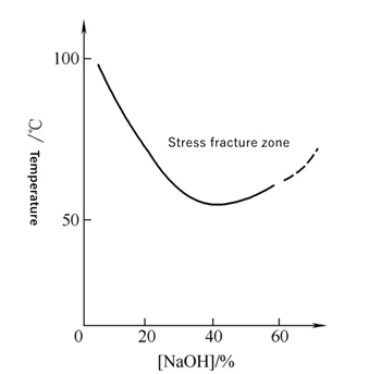
When sodium hydroxide concentration is more than 5%, carbon steel and low alloy steel steam pipelines are almost likely to produce caustic crackings, alkali stress corrosion generally occurs at more than 50~80℃, especially near the boiling point of high temperature area, alkali concentration of 40% ~ 50%. According to the theory, when the mass fraction of local NaOH is greater than 10%, the protective oxide film of the metal will be dissolved, and the matrix metal will react with the alkali further to form loose and porous magnetic corrosive oxides, and the aqueous solution is alkaline. As long as 10~20mg·L-1 NaOH is contained in the water of boiler or heat exchanger, local repeated evaporation can lead to the concentration of alkali under the sediment or in the crevices, causing local alkali corrosion.

The factors affecting the sensitivity of caustic cracking

Caustic cracking is easy to occur in the concentrated parts of alkali containing liquid with high residual stress, such as welding joint parts, this type of SCC is usually developing intergranular and the fractures are filled with oxides.

The alkali-brittle cracks in the carbon steel steam pipeline appear as fine intergranular cracks with oxides. There are several main factors that determine the brittleness of alkali: alkali concentration, metal temperature and tensile stress. Experiments show that some caustic cracking occurs within a few days, while most occur when exposed to more than 1 year. Increasing the alkali concentration and temperature can improve the cracking rate.

Medium 

Caustic cracking is the corrosion that occurs at high temperatures in concentrated lye. When the mass fraction of NaOH is lower than 5%, there won’t cause caustic cracking. This concentrated lye can be the working medium or can be gathered during. The higher the concentration of caustic soda, the greater the sensitivity of caustic cracking, which is not only related to the concentration of the alkali but also depends on the temperature of the solution.

The temperature

The cracking fracture time of low carbon steam pipeline steels increases with the decrease of stress. It is found that the metal in the heat-affected zone with the largest residual plastic deformation, that is, the metal heated to 500~850℃ in the welding process, has the largest SCC tendency. It was found in the maintenance of alkali equipment that the metals heated at temperatures over 550℃ and slightly lower than the recrystallization zone during welding had the greatest cracking tendency in alkaline solution, where the welding residual stress and microstructure stress are the largest.

Metal elements

Because the caustic cracking and nitrate brittleness of low carbon steel is fractured along the grain, it is theorized that the sensitivity of such brittleness is caused by the segregation of C, N and other elements at the grain boundary. The chemical elements that cause the caustic cracking of low carbon steam pipeline steel are as follows:

▪ C and N segregation at grain boundaries increases the caustic cracking sensitivity;

▪ The effect of trace elements, due to the segregation of S, P, As and other impurities at grain boundaries increase alkali embrittlement sensitivity. However, a small amount of La, Al, Ti and V may be due to reducing the segregation of harmful impurities in the grain boundary reducing the alkali embrittlement sensitivity.

▪ The caustic cracking increases as grain size increase,;

▪ Heat treatment. The caustic cracking sensitivity of the steel after spheroidizing is greater than that of the normalized state, which may be due to the increase of grain boundary segregation during the spheroidizing of carbides.

Potential 

The sensitive potential of caustic cracking of low carbon steam pipeline steel in boiling 35%~40% NaOH solution is -1150~800mV (SCE), and the potential of caustic cracking occurs in the range of -700mV (SCE) at boiling point (120℃). At the critical potential, the section shrinkage of the sample decreases greatly. The X-ray structure analysis shows that the Fe3O4 protective film is formed on the surface of the sample.

What’s the epoxy coal tar coated steel pipe used for?

Epoxy coal tar is a kind of ] corrosion prevention coatings with excellent impact resistance and water resistance, consist by the modified epoxy resin, polyamide resin, coal tar, fillers and additives, offering excellent water resistance, microbial corrosion resistance, good adhesion, toughness, moisture resistant. It can prevent all kinds of ion etching, has been widely used in steel used in underground oil pipeline, water pipe, anticorrosion of sewage pipes, etc. Epoxy coal asphalt anticorrosive layer is divided into general anticorrosive, enhanced anticorrosive (one layer three oil) and special enhanced anticorrosive (two layer four oil). Epoxy coal tar asphalt anticorrosive steel pipe is an anticorrosive form of glass cloth layer and anticorrosive coating. The high quality epoxy coal tar with anticorrosive coating has smooth surface, close adhesion with glass cloth, not easy to peel off, and will not have strong pungent smell after complete drying.

Applications

Because the sheet-shaped iron pigment contained in the coating and the primer matching, which can form a dense, solid, impermeable coating, so the epoxy coal pitch anticorrosive coating also has low water vapor permeability and excellent water resistance, can be used for ship bottom, ballast tank, wharf steel pile, mine steel support, acid tank, water pipeline and industrial and mining cooling water pipeline wall anti-corrosion, anti-corrosion and leakage of underwater steel structure and cement components, underground pipeline and gas storage tank under the protection; Coastal and salt fields in high temperature areas; Anticorrosion of internal and external walls of chemical and other pipelines. At the same time, it is also suitable for long years of wet environment like sewages treatment or construction environment wet substrate surface and coating requirements toughness of the higher parts.

Storage and Transportation

1. If it cannot be used in time, it should be stored indoors to avoid sun damage to the coating; UV-proof shielding should be used if outdoors.

2. Construction should be carried out under good ventilation conditions. Open fire is strictly prohibited on site;

3. Pay attention to the change of climate and temperature. It is not suitable for construction in the environment of rain, fog, snow or relative humidity greater than 80%.

Construction temperature should be greater than 10℃;

4. Violent collision, extrusion and storage shall be prohibited in the process of transportation.

The design of steel pipe piling

Steel pipe pile foundation has the characteristics of quick construction, safety and highly mechanized operation, and is often widely used in large offshore bridges, substructures of ports and wharves, temporary platforms and trestles, etc. Compared with reinforced concrete foundation, steel tube pile foundation has the following advantages:

  • Lightweight, high strength, convenient loading and transportation;
  • High bearing capacity. The steel can be effectively driven into the hard soil and the pile body is not easy to damage and can obtain a great single pile bearing capacity;
  • The length is easy to adjust, can be adjusted by connecting or cutting according to the need.
  • A small amount of soil discharge. The lower end of the pile is open. With the driving of the pile, the soil squeezing volume of the pile pipe is greatly reduced compared with that of the solid core concrete pile, and the disturbance to the surrounding foundation is less and the displacement is less.
  • It can be welded, easy to operate and fast to construct.

Steel pipe piles are generally made of plain carbon steel, with a tensile strength of 402MPa and yield strength of 235.2MPa, or according to the design requirements. It can be an SSAW pipe and an LSAW pipe. SSAW steel pipe has high rigidity and is commonly used. In order to facilitate transportation and be limited by pile frame height, steel pipe piles are usually composed of an upper section pile, a lower section pile and several middle section piles respectively. The length of each section is generally 13m or 15m, as shown in the figure:

A) Lower section pile;

(b) Mid-section pile;

(c) Upper section pile

The lower end of the steel pipe pile is divided into opening and closing. Its structure and type are shown in the figure below:

The diameter of the steel pipe pile is φ406.4-φ2032.0mm, and the wall thickness is 6-25mm.

We should take the engineering geology, load, foundation plane, upper load and construction conditions into consideration. Commonly used specifications are 406.4mm, 609.6mm and 914.4mm, wall thickness 10, 11, 12.7, 13mm, etc. Generally, upper, middle and lower section piles usually adopt the same wall thickness. Sometimes, in order to make the pile top bear the huge hammer impact and prevent the radial instability, the wall thickness of the upper section of the pile should be appropriately increased, or a flat steel reinforcement collar 200~300mm wide and 6~12mm thick should be added to the outer ring of the pile pipe. In order to reduce the friction resistance of the pile pipe sinking and prevent the end from being damaged due to deformation when penetration into the hard soil layer, a strengthening collar is also set at the lower end of the steel pipe pile. For Φ406.4 ~ Φ914.4mm steel pipe, the size of the strengthening pipe collar is 200~300mm*6~12mm.

(a) Structural forms of steel tube pile joints with different wall thicknesses;

(b) Reinforcement collar on top of piles;

(c) Reinforcement collar at the lower end of the pile

The accessories of steel pipe piles mainly include a pile cover welded on top of the pile for bearing the upper load, flat steel strip, a protective ring at the bottom of the pile, and a copper clamp welded on the pile joint. In order to reduce the negative friction of soft soil foundation on the bearing capacity of piles, a layer of special asphalt, polyethylene and other composite materials are coated on the outer surface of the upper end of the steel pipe pile to form a sliding layer of 6~10mm, reducing the negative friction by 4/5-9/10.

Structure of sliding layer of steel pipe pile:

1 Steel pipe pile;

2 Primer coating;

3 Sliding layer;

4 Surface

The specifications of steel pipe pile

In the offshore and inland alluvial plain region, the thickness of 50 ~ 60 m soft soil layer of the upper load is big and can not directly as a bearing layer, the low compression bearing layer is always deep, where usually use the general structure of steel pile with a pile hammer producing a large impact on it. Steel pipe pile reinforcing foundations are suitable than conventional reinforced concrete and prestressed concrete pile at this time.

Steel Pipe Pile is generally made of spiral welded steel pipe by plain carbon steel plate. At present, steel pipe piles are mainly used in offshore areas environment were surrounded by deep water and the large impact force of waves, currents and ships. The steel pipe pile has a series of advantages like high strength and great bending resistance. Good elasticity, can absorb large deformation, reduce the ship to the dock building impact force; Convenient construction, can speed up the construction progress of wharf facilities. Here are the commonly used specifications of steel pipe piles.

How to improve the strength of steel?

The strength of steel refers to the deformation and fracture performance of metal materials under the action of external force, which generally includes tensile strength, bending strength and compressive strength. The more resistant steel is to external forces, the stronger the steel will be. So how can we improve the strength of steel?

Solution Strengthening

The solid solution of alloying elements in the matrix metal causes certain lattice distortion and increases the strength of the alloy. Lattice distortion increases the resistance of dislocation movement and makes it difficult to slip, thus increasing the strength and hardness of the alloy solid solution. This phenomenon of strengthening a metal by dissolving into a solute element to form a solid solution is called solid solution strengthening.

The strength and hardness of the material are increased with the proper concentration of solute atoms, but the toughness and plasticity are decreased. The higher the atomic fraction of solute atom is, the greater the atomic size difference between solute atom and matrix metal is, and the stronger the strengthening is. 

The interstitial solute atoms have a greater solution strengthening effect than the substitutive atoms, and the strengthening effect of interstitial atoms is greater than that of face-centered cubic crystals because the lattice distortion of interstitial atoms in body-centered cubic crystals is asymmetric. However, the solid solubility of interstitial atoms is very limited and the actual strengthening effect is also limited. The larger the difference in the number of valence electrons between the solute atom and the substrate metal is, the more obvious the solution strengthening is, that is, the yield strength of the solid solution increases with the increase in the concentration of valence electrons.

Work Hardening

With the increase of cold deformation, the strength and hardness of metal materials increase, but the plasticity and toughness decrease. Cold work hardening is the phenomenon that the strength and hardness of metal materials increase while the plasticity and toughness decrease during plastic deformation below the recrystallization temperature. Because the metal in the plastic deformation, grain slip, dislocation causes grain elongation, fragmentation and fibrosis, the metal internal residual stress. Work hardening is usually expressed by the ratio of the microhardness of the surface layer after machining and before machining and the depth of the hardening layer.

Work hardening can improve the cutting performance of low carbon steel and make the chip easy to separate, but it brings difficulties to the further machining of metal parts. For example, in the process of the cold-rolled steel plate and cold-drawn steel wire, the energy consumption of drawing is increased and even is broken, so it must be through intermediate annealing to eliminate work hardening. In the cutting process to make the surface of the workpiece brittle and hard, increase the cutting force and accelerate tool weariness, etc.

It improves the strength, hardness and wear resistance of steels, especially for those pure metals and some alloys whose strength cannot be improved by heat treatment. Such as cold drawn high strength steel wire and cold coil spring, is the use of cold processing deformation to improve the strength and elastic limit. The track of tank, tractor, and the turnout of railway also use work hardening to improve its hardness and wear resistance.

Fine-grain Strengthening

The method of improving the mechanical properties of metal by refining grain is called fine grain strengthening. We know that a metal is a polycrystal composed of many grains, and the size of the grains can be expressed by the number of grains per unit volume. The more the number, the finer the grains. The experiments show that the fine grain metal has higher strength, hardness, plasticity and toughness than the coarse grain metal at normal temperature. This is because the fine grains can be dispersed in more grains when plastic deformation occurs under external force, so the plastic deformation is more uniform and the stress concentration is small.

In addition, the finer the grain is, the larger the grain boundary area is, and the more tortuous the grain boundary is, the more disadvantageous the crack propagation is. Therefore, the industrial method to improve the material strength by refining grain is called fine grain strengthening. The more grain boundaries are, the smaller the stress concentration is, and the higher the yield strength of the material is. Methods to refine the grain include: increasing the degree of supercooling;

Metamorphic treatment;

Vibration and agitation;

Cold-deformed metals can be refined by controlling the degree of deformation and annealing temperature.

Second Phase Strengthening

In addition to the matrix phase, the second phase exists in the multiphase alloy compared with the single-phase alloy. When the second phase is distributed uniformly in the matrix phase as finely dispersed particles, the strengthening effect will be significant. This strengthening is called second phase reinforcement. For the dislocation movement, the second phase of the alloy has the following two conditions: (1) reinforcement by an indeformable particle (a bypassing mechanism). (2) The strengthening effect of deformable particles (a cutting mechanism).

The dispersion strengthening and precipitation strengthening both belong to the special cases of the second phase strengthening. The main reason for the strengthening of the second phase is the interaction between them and the dislocation, which hinders the dislocation motion and increases the deformation resistance of the alloy.

In general, the most important thing that affects the strength is the composition of the metal itself, the organizational structure and the surface state, followed by the stress state, such as the speed of the after force, the loading method, the simple stretching or repeated stress, they will show different strength; In addition, the shape and size of the metal and the test medium also have an effect, sometimes even decisive, such as the tensile strength of ultra high strength steels may be reduced exponentially in a hydrogen atmosphere.

There are two main ways to improve the strength: one is to improve the interatomic bonding force of the alloy to improve its theoretical strength, and to produce a complete crystal without defects such as whiskers. The strength of the known iron whiskers is close to the theoretical value, which can be assumed to be due to the lack of dislocations in the whiskers or to the fact that they contain only a small number of dislocations that cannot proliferate during deformation. However, when the diameter of the whisker is large, the strength will decrease sharply. Secondly, a large number of crystal defects are introduced into the crystal, such as dislocation, point defects, heterogeneous atoms, grain boundaries, highly dispersed particles or inhomogeneity (such as segregation), etc. These defects hinder the dislocation movement and significantly improve the metal strength. This proved to be the most effective way to increase the strength of the metal.

SSC VS HIC Tests

Sulfide stress cracking (SSC) is a form of hydrogen embrittlement cracking. Sulfide stress cracking occurs in low alloy steel pipeline, high-strength steels, weld joints, and welding heat-affected zones (HAZs) subjected to tensile stress in acidic environments and temperatures below 82°C (180°F), depending on the composition, microstructure, strength, residual stress, and external stress of the steel.

The steel plate samples were immersed in an acidic aqueous solution containing H2S, and the anti-SSCC performance data were obtained by applying an appropriate incremental load. According to the standard NACE TM0177-2016, the specific requirements are as follows: take a group of forged steel plate sample σb or Hb to be the highest, carry out anti-sulfide stress cracking test, and the stress σTh ≥247MPa to be qualified. A group of samples from class A, B and D welded joint samples were taken for sulfide stress cracking test, and the stress σTh ≥247MPa was considered qualified.

Hydrogen induced cracking (HIC) is a kind of internal cracks with stepped characteristics formed by the interconnection of parallel hydrogen layer cracks, which have no obvious interaction with external stress or residual stress. At the bubbling part, hydrogen cracking is aggravated by the stress generated by hydrogen accumulation inside. HIC is closely related to the cleanliness of steel, as well as the manufacturing method of steel, the presence of impurities and their shape.

HIC occurs in thin and heterogeneous sulfide or oxide inclusions occurring parallel to the rolling direction of the steel plate. These inclusions form sites that form microscopic hydrogen bubbles and eventually grow together through step-like fractures. Since HIC is not stress-dependent and does not occur with hardened microstructure, post-weld heat treatment is not meaningful. The resistance to hydrogen cracking can only be achieved by limiting trace element sulfur and controlling the manufacturing variables of steel.

SSC and HIC tests are based on the NACE international test standard recommended by the American Society of Corrosion Engineers. Constant load stress corrosion test and three-point bending test were mainly used for SSC test, mainly according to NACE TM0177, and NACE TM0284 was mainly used for HIC test. The materials used in the design and manufacture of the elastic design criteria may be selected from those already qualified in ISO 15156-2 and ISO15156-3 or NACE_MR0175 standards, which have specified environmental conditions to avoid stress corrosion. The materials should be selected only if they meet this limitation.

Conditions for exemption from SSC and HIC tests for carbon steel, low alloy steel and cast iron

1. Materials shall be delivered in the following conditions:

Hot rolling (carbon steel only)/annealing/normalizing/normalizing + tempering/normalizing, Austenitizing, quenching + tempering/Austenitizing, quenching + tempering

2. Material hardness is not more than 22HRC, and nickel content is less than 1.0%;

S 0.003% or less, P 0.010% or less;

The hardness of weld and heat affected zone shall not exceed 22HRC.

3. The yield strength of the material is less than 355Mpa and the tensile strength is less than 630Mpa

4. Carbon equivalent limit:

Low carbon steel and carbon manganese steel: Ce ≤0.43 Ce =C+Mn/6

Low alloy steel: Ce ≤045 Ce =C+Mn/6+(Cr+Mo+V)/5+(Ni+Cu)/15

Conditions for exemption from SSC and HIC tests for stainless steel

CCrNiPSMnSi
≤0.08≥16.00≥8.00≤0.045≤0.04≤2.0≤2.0
Chemical composition limitation
  1. The content of 321 stainless steel with higher carbon content allowed to contain other elements is acceptable within the corresponding technical range.

2. Should be solution annealing and quenching, or annealing heating stabilized heat treatment conditions;

3. It is not allowed to improve mechanical properties through cold working;

4. The hardness of raw materials, welds and heat affected zone shall not exceed 22HRC.

Alloy UNS.NoTemperature, maxPressure H₂S, kpa(psi)Chloride ion concentration(mg/l)PhSulphate resisting
S3160093(200)10.2(1.5)5000≥5.0No
S31603149(300)10.2(1.5)1000≥4.0No
S2091066(150)100(15)//No

The welding of API J55 casing

API 5A J55 is a commonly used casing material. The tubing body is threaded to the coupling and must be welded to reinforce the strength of the threaded connection. A harsh working environment requires high quality for the pipe body and welding quality. We analyze its weldability by calculating carbon equivalent. The chemical composition of J55 casing is shown in the following table:

CSiMnPSCrNiCu
0.34~0.390.20~0.351.25~1.50≤0.025≤0.015≤0.15≤0.20≤0.20
J55 Casing tubing chemical composition

CE=C+Mn/6+(Cr+Mo+V)/5+(Ni+Cu)/15

CE=0.69>0.4

The weldability of the material is poor when the carbon equivalent exceeds 0.4, high preheating temperature and strict process are needed to obtain qualified welding quality. The carbon content of 0.34%~0.39% makes the transition curve of supercooled Austenite shift to the right, and the stability of supercooled Austenite increases. The addition of alloying elements, such as Cr, Mn, Ni and Cu, makes the transition curve of supercooled Aaustenite shift to the right, and enhances its stability and MS point (the beginning point of Mmartensite formation). All these effects increase the quenching tendency of J55, and it is easy to crack during welding.

The cold crack tendency of J55 casing is mainly due to the large quenching embrittlement crack. The highest hardness value of welding heat affected zone is high and the rapid cooling is easy to form martensite because of the high strength. In order to reduce the cooling rate, extend the cooling time of the welded joint from 800 ℃ to 500℃, improve the microstructure of the weld metal and reduce the maximum hardness of the heat-affected zone, preheating before welding and tempering after welding is required. J55 casing has a small hot crack tendency because it does not contain strong carbide and has low thermal conductivity, which is difficult to generate low fusion eutectic. The tensile strength of J55 is greater than or equal to 517 MPa, and the yield strength is 379-522MPa. we should use welding wire ER55-G which has similar strength. The welding wire has high welding Ni content, strong cold cracking resistance, and excellent comprehensive mechanical properties of the deposited metal. Our engineers make the following two plans:

Welding method 1: 80%Ar+20%CO2 gas welding. ER55-G welding wire with a diameter of 3.2mm. Welding parameters: current 250~320A, voltage 26 ~30V; Welding speed 35~50cm/min; The preheating temperature is 100℃, and the inter-layer temperature is not lower than the preheating temperature, but it is not allowed to be higher than the preheating temperature of 30℃. Post-welding treatment: air cooling without any heat treatment.

Welding method 2: The same welding materials and welding parameters as method one, only the change of post-welding heat treatment: tempering treatment, temperature 600±20℃, holding time for 4h; Heating rate 50℃/h, cooling rate 50℃/h.

The results of the two welding tests are as follows:

The tensile test of the first scheme is qualified. The impact values of the three samples in the heat-affected zone are 26,47,23, which are unqualified. The four lateral bending samples had cracks of 3.75mm, 4mm, 1.38mm and 0.89mm, respectively, which were unqualified. The test shows that this welding scheme is not reasonable.

The second scheme is qualified by tensile test; The impact values of the three samples in the heat-affected zone are 51,40,40, which are qualified. All the four side bending samples are intact and qualified; The experiment proves that this welding scheme is reasonable. Post-welding heat treatment can improve the welding microstructure and properties, which is one of the important factors for obtaining the welded joints that meet the technical requirements of J55 casing welding.

What’s the steel material for Hydrogen pipeline?

Hydrogen can be gaseous hydrogen, liquid hydrogen and solid hydrogen according to the state when transportation, among which high-pressure gaseous hydrogen is the most commonly used and environmentally friendly transportation mode at present. Pipeline transportation is the most efficient way for a large throughput and distance occasions can be a long-distance pipeline, also be a short distance distribution pipeline. The long-distance transmission pipeline has high pressure and large diameter, which is mainly used for conveying high-pressure hydrogen between hydrogen production unit and hydrogen station. The latter pipeline is low-pressure and a small diameter is mainly used for the distribution of medium and low-pressure hydrogen between the hydrogen station and end-user. The current cost of long-distance hydrogen pipelines is about $630,000 / km, compared with $250,000 / km for natural gas pipelines, 2.5 times the cost of natural gas pipelines, then comes with the question, how to choose the right material for the transportation of Hydrogen pipeline?

Compared with natural gas, metal materials working in a hydrogen environment for a long time will cause the deterioration of mechanical properties, which is called environmental hydrogen embrittlement. The evaluation of high-pressure hydrogen embrittlement properties of metals is mainly conducted through in-situ hydrogen environment tests, in which materials are directly placed in a hydrogen environment. The types of tests mainly include slow strain rate tensile test, fracture toughness test, crack growth rate test, fatigue life test and disc pressure test. The hydrogen embrittlement can be determined according to No.NASA8-30744 standard and the resistance of materials to hydrogen embrittlement can be evaluated according to ASTM G142-98 comparison of sensitivity test results.

Compared with natural gas pipelines, hydrogen pipelines are different in alloy elements, steel grade, pipe shape and operating pressure due to the limitation of hydrogen embrittlement in the environment. The available materials for natural gas pipelines specified in ASME B31.8-2018 include all the steel pipes in API SPEC 5L. However, in practical engineering, to reduce the wall thickness of pipelines, high-strength steel pipes are generally preferred, and commonly used pipe types include SAWL, SAWH, HFW and SMLS. For hydrogen gas pipeline, a hydrogen environment induced by hydrogen embrittlement occurred, in turn, can lead to pipeline failure, that depends on the steel pipe molding process, weld quality, defect factors such as size, steel strength, so the ASME B31.12-2014 in API SPEC 5 l limited several hydrogens can be used for pipeline steel type, indicating to ban the use of furnace tube welding, pipeline steel specified in the standard can be used in the hydrogen pipe and the maximum allowable pressure as shown in the table below.

API 5LX42X52X56X60X65X70X80
Yield strength /Mpa289.6358.5386.1413.7488.2482.7551.6
Tensile Strength /Mpa413.7455.1489.5517.1530.9565.4620.6
Allowable Pressure, Max 20.6820.6820.6820.6810.3410.3410.34

Alloying elements such as Mn, S, P and Cr can enhance the hydrogen embrittlement sensitivity of low alloy steels. At the same time, the higher the hydrogen pressure and the higher the strength of the material, the more obvious hydrogen embrittlement and hydrogen-induced cracking will be. Therefore, in practical engineering, low steel grade steel tubes are preferred for hydrogen pipelines. ASME B31.12-2014 recommends the use of X42, X52 steel pipes, and stipulates that hydrogen embrittlement, low temperature performance transition, ultra-low temperature performance transition and other issues must be considered.

International standardization organizations include the International Hydrogen Technical Committee (ISO/TC197), the European Industrial Gas Association (EIGA) and the American Society of Mechanical Engineers (ASME) and another organization specifies standards for the production, storage, transportation, testing and use of hydrogen energy, mainly includes ASMEB31.12-2014 “Hydrogen Pipelines”, CGAG-5.6-2005 “Hydrogen Pipeline Systems”, which are suitable for the design of long Hydrogen Pipeline and short distance Hydrogen delivery Pipeline. Hydrogen pipelines are mostly made of seamless steel pipes. The hydrogen pressure is generally 2~10MPa, the diameter of the pipes is 0.3~1.5m, and the pipeline materials are mainly X42, X52, X56, X60, X65, X70, X80 and other low strength pipeline steels. The expected service life is 15~30 years.

Line Pipe for Gas, Oil, and Water Pipelines

Line Pipe for Gas, Oil, and Water Pipelines

Line pipe is a type of steel pipe that is used for transporting materials through pipelines across the country. Line pipe can be used to transport petroleum, natural gas, oil, and water. It is a durable pipe that must meet certain specifications and regulations. This pipe typically has a high strength and durability in order to withstand high pressures. At Wldsteel, we sell and distribute line pipe in a complete variety of sizes, lengths, diameters, and grades.

Line Pipe for Gas, Oil, and Water Pipelines

To learn more about our line pipe sales and distribution services or to receive a quote for your specific requirements, please

What is Line Pipe
Line pipe is a type of pipe that is manufactured from high strength carbon steel. It is typically made according to metallurgical specifications that were developed by the American Petroleum Institute (API). Line pipe can be used to build pipelines that transport a variety of resources including natural gas, oil, petroleum, and water. This pipe is available in a variety of diameters ranging from 2 inches to 48 inches. Line pipe can include either seamless or welded carbon steel or stainless steel piping. Because line pipe needs to withstand high pressures, there are important tests done on line pipe to ensure it meets all of the requirements of steel chemistry, strength, toughness, and dimensional characteristics. Using line pipe that meets the set criteria will ensure safe and reliable pipeline service.

The size and diameter of line pipe that is required for a pipeline can vary based on the amount of gas or liquid that a pipe is intended to carry as well as the pressures that a line pipe must withstand. For example, in most cases a mainline, the principal pipeline that delivers natural gas, will require line pipe that is around 16 to 48 inches in diameter. Smaller pipelines that deliver gas to the mainline or take gas from a mainline can be constructed of 6 to 16 inch diameter line pipe. One can determine the necessary diameter required for a pipeline by considering the volume of gas or liquid that the line pipe will be carrying as well as the pressure at which this will be transported.

The thickness requirements for line pipe are determined by the maximum operating pressure required for a pipeline. This is based on published standards and federal regulations. Following proper safety regulations when selecting and installing line pipe, will ensure proper pipeline operation and prevent dangerous or hazardous situations.

Buy Line Pipe
At Wldsteel, we sell carbon steel line pipe and  stainless steel pipe in a variety of sizes, diameters, and thicknesses. This line pipe can be used for pipelines that carry oil, petroleum, natural gas, or water. Most sizes of our ERW, DSAW and Seamless Steel pipe are available with mill test reports and full traceability as required. We can supply many grades of line pipe, including API 5L-B, X-42, X-46, X-52, X-60, X-70 and higher.

As a leading pipe distributor, we are not only able to supply new line pipe direct from stock or mill sources, but we can also cut pipe to your required length and add special coatings as needed. We can deliver line pipe and other stainless steel piping to nearly any worksite or location throughout the United States. To learn about our current selection of line pipe for sale or to learn more about our stainless steel pipe distribution services, please feel free to contact us at WLD Steel.

Steel line pipe for oil & gas

Steel line pipe for oil & gas

What is Line Pipe:

Line pipe is a type of pipe that is manufactured from high strength carbon steel. It is typically made according to metallurgical specifications that were developed by the American Petroleum Institute (API). Line pipe can be used to build pipelines that transport a variety of resources including natural gas, oil, petroleum, and water. This pipe is available in a variety of diameters ranging from 2 inches to 48 inches. Line pipe can include either seamless or welded carbon steel or stainless steel piping. Because line pipe needs to withstand high pressures, there are important tests done on line pipe to ensure it meets all of the requirements of steel chemistry, strength, toughness, and dimensional characteristics. Using line pipe that meets the set criteria will ensure safe and reliable pipeline service.The size and diameter of line pipe that is required for a pipeline can vary based on the amount of gas or liquid that a pipe is intended to carry as well as the pressures that a line pipe must withstand. For example, in most cases a mainline, the principal pipeline that delivers natural gas, will require line pipe that is around 16 to 48 inches in diameter. Smaller pipelines that deliver gas to the mainline or take gas from a mainline can be constructed of 6 to 16 inch diameter line pipe. One can determine the necessary diameter required for a pipeline by considering the volume of gas or liquid that the line pipe will be carrying as well as the pressure at which this will be transported.The thickness requirements for line pipe are determined by the maximum operating pressure required for a pipeline. This is based on published standards and federal regulations. Following proper safety regulations when selecting and installing line pipe, will ensure proper pipeline operation and prevent dangerous or hazardous situations.

Steel line pipe for oil & gas

TYPES OF OIL & GAS PIPES
Steel pipes can be classified according to multiple criteria, such as:

Manufacturing process: seamless, erw, LSAW, DSAW, HSAW pipes
Finishing: cold rolled, hot rolled, cold finished
Materials: metal, plastic, cement, glass, fiberglass, etc and material grades (carbon steel, stainless steel, nickel alloy steel pipes)
Manufacturing norms

Line pipe sizes, grades and dimensions
Nominal pipe sizes (NPS) and diameters differ on the transported amount of gas or other flammable liquid as well as the pressures it has to withstand. The outside diameter (OD) of line tubes ranges from 1/8″ to 80″ in accordance with API 5L and other international standards (DIN, ASTM/ASME, NFA, EN) and grades (A / B / X-42 / X-46 / X-52 / X-56 / X-60 / X-65 / X-70 / X-80). Industry standards and federal regulations also specify wall thickness that is determined by the maximum operating pressure (MAOP). Further detailed information is displayed in our line pipe product chart.

standard of Steel line pipe for oil & gas

  • API 5L/ISO 3183 Gr. A, B, X42, X46, X52, X56, X60, X65, X70, X80
  • ASTM A134 and ASTM A135
  • CSA Z245.1 Gr. 241, 290, 359, 386, 414, 448, 483, 550

Dimensional Tolerances for Line Pipes to API Specification 5L / ISO 3183

Pipe SizeDiameter Tolerances
Pipe oxeept the endPipe end 1)
Mrtmir,ai Specified Outside Nominal Pipe Size Djam〇terseamless weldedseamless welded
Up to 2″ Up to 60.3 mm-0.8 mm / + 0.4 mm-0.4 mm / + 1.6 mm
c. . . 60.3 mm up to 2 t6.._nd. 168.3mmjncl.± 0.0075 D
6*to24*,incl. 168.3 mm up to 610 mm. incl.+/- 0.0075 D±0.0075 D butmaximum of *3.2+/- 0.005 D. but maximum of +/-1.6 mm
26′ up to 56″, incl. 660 up to 1422 mm incl.+/- 0.01 D± 0.005 D but maximum of ±4.0+/- 2.0 mm+/-1.6 mm
Over 56* Over 1 422.0 mmas agreed

Pipeline System Supply delivers line pipe for onshore and offshore applications in the oil and gas industry used to convey natural gas, oil and other flammable fluids. Due to extreme conditions such as low and high temperature, high pressure and corrosive environments in the transportation of flammable media, line tubes are made from carbon, alloy or stainless steel in accordance with API 5L, EN and ISO 9001 standards. International standards determine metallurgical specifications to guarantee safe, reliable and long lasting pipelines. Therefore important tests are performed on line pipe to ensure it meets all of the determined requirements of steel chemistry, strength, toughness, and dimensional characteristics. Steel pipes can be manufactured seamless and in different welded varieties ranging from Fusion Welded (EFW), Electric Resistance Welded (ERW), High Frequency Induction (HFI) to Double Submerged Arc Welded (DSAW).