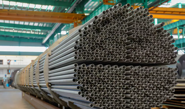
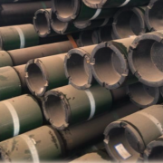
The weldability of J55 oil casing

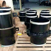
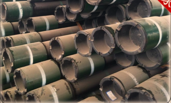
The oil casing is composed of a collar and pipe body. A single pipe body is connected with the collar thread and transported to the oil field site with end to end connection to facilitate transportation and use after reaching the required length. In order to strengthen the strength and anti-loosening control of the threaded connection, it is necessary to weld the coupling with the pipe body after the threaded connection, so it is very important to analyze the welding performance and formulate a reasonable welding process. API 5A J55 is one of the most commonly used casing materials, and we analyzed its weldability in terms of its carbon equivalent.

API 5CT J55 Chemical Composition

GradeCSiMnPSCrNiCuMo
API 5CT J550.34-0.390.20-0.351.25-1.500.0200.0150.150.200.20/

According to the carbon equivalent formula of the International Institute of Welding:

CE=C+Mn/6+(Cr+Mo+V)/5+(Ni+Cu)/15

CE=0.69>0.4

Its carbon equivalent is more than 0.4 and its weldability is poor. In order to obtain qualified welding quality, high preheating temperature and strict technological measures are needed.

Its weldability was analyzed according to the influence of J55 alloy element content on microstructure and properties:

  • J55 casing tube has a high carbon content, that’s 0.34%~0.39%, which makes the supercooled austenite transition curve of steel move to the right and increase; The addition of Cr, Mn, Ni, Cu and other alloy elements makes the transition curve of supercooled austenite shift to the right, which enhances the stability of the supercooled austenite, and increases the MS point (the beginning point of martensite formation). All these effects increase the quenching tendency of J55, and welding cracks have appeared.
  • J55 has a large tendency to cold crack, mainly quenching and embrittlement crack. Due to its high strength, high maximum hardness value of welding heat affected zone and rapid cooling, martensite is easily generated. When welding, try to choose large line energy and welding current, should not excessively reduce the welding speed. In order to reduce the cooling rate, extend the cooling time of the welded joint from 800 ℃ to 500℃, improve the microstructure of the weld metal and the heat-affected zone, and reduce the maximum hardness of the heat-affected zone, preheating before welding and tempering after welding is required.
  • The hot crack tendency of J55 is not high because its thermal conductivity is not easy to generate low fusion eutectic; The reheat crack tendency is not large, because it does not contain strong carbide. The welding wire ER55-G matched with its strength is selected. The welding wire has excellent welding process performance, high Ni content, strong cold crack resistance, and excellent comprehensive mechanical properties of the deposited metal.
  • Due to the large heat input required for J55 welding, the strength value of base material and welding material is large, and the internal stress during welding is extremely large. During welding, it is necessary to hammer the weld while welding. After welding, heat treatment is carried out to eliminate the internal stress and avoid the post-welding cracking caused by excessive stress. Post-weld heat treatment can also improve the welding microstructure properties.

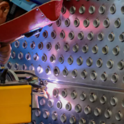
Welding process of J55

Welding method 1: 80% Ar+20%CO2 gas shielded welding. Welding material: welding wire ER55-G, diameter Φ3.2mm. Welding parameters: current 250~320A, voltage 26 ~30V; Welding speed 35~50cm/min;

The preheating temperature is 100℃, and the interlayer temperature is not lower than the preheating temperature, but it is not allowed to be higher than the preheating temperature of 30℃.

Post-welding treatment: air cooling without any heat treatment.

Results: The tensile test was qualified. The impact values of the three samples in the heat-affected zone are 26,47,23, unqualified. The four side bending samples have 3.75mm crack, 4mm crack, 1.38mm crack, 0.89mm crack, respectively, which are unqualified. This technological scheme is not reasonable.

Welding method 2: 80%Ar+20%CO2 gas welding. Welding material: welding wire ER55-G, diameter Φ3.2mm. Welding parameters: current 250~320A, voltage 26 ~30V; Welding speed 35~50cm/min; The preheating temperature is 100℃, and the interlayer temperature is not lower than the preheating temperature, but it is not allowed to be higher than the preheating temperature of 30℃.

Post-welding treatment: tempering treatment, temperature 600±20℃, holding time for 4h; Heating rate 50℃/h, cooling rate 50℃/h.

Results: The tensile test was qualified. The impact values of the three samples in the heat-affected zone are 51, 40 and 40, respectively, which are qualified.

Side bending test, qualified; The experiment proves that this technological scheme is reasonable. Post-welding heat treatment can improve the welding microstructure and properties, which is one of the important factors for J55 welding to obtain the welded joints that meet the technical requirements.

The harsh API 5A J55 casing environment requires the quality of the pipe itself, also the quality of the welding. Through the above welding analysis and test, the welding process that can meet the requirements is obtained, which provides a theoretical and experimental basis for the correct welding of oil casing.

Advantages of U tube heat exchanger

U tube heat exchanger is characterized by its simple structure, good tightness, convenient maintenance and cleaning, low cost, good thermal compensation performance and strong pressure bearing capacity. The U-tube heat exchanger has the largest heat exchange area under the same diameter. The main structure of U-shaped tube heat exchanger includes tube box, cylinder, head, heat exchange tube, nozzles, baffle, anti-shock plate and guide tube, anti-short circuit structure, support and other accessories of the shell and tube side, is the most commonly used in shell and tube heat exchanger.

Heat exchange tube

Heat exchange tubes used for heat transfer usually use primary cold-drawn heat exchange tubes and ordinary cold-drawn heat exchange tubes. The former is suitable for heat transfer and vibration occasions without phase change, and the latter is suitable for reboiling, condensing heat transfer and vibration-free general occasions. The heat exchanger pipe shall be able to withstand certain temperature differences, stress and corrosion resistance. The length of the heat exchange tube is generally 1.0m, 1.5m, 2.0m, 2.5m, 3.0m, 4.5m, 6.0m, 7.5m, 9.0m, 12.0m. The material of the pipe can be carbon steel, stainless steel, aluminum, copper, brass and copper-nickel alloy, nickel, graphite, glass and other special materials, also often used composite pipe. In order to expand the area of effective heat transfer tube at the same time maximize the tube side heat transfer coefficient, heat exchange tube processing or in tube inserted into the internal and external surfaces of the disturbed flow components, producing fluid turbulence the inside and outside at the same time, commonly used such as rough surface tubes, finned tube, the supporting pipe, inside the plug-in type, etc.

Tube sheet

Tube sheet is one of the most important parts of shell – tube heat exchanger. The tube plate is the barrier between the shell side and the pipe side. When the heat exchange medium has no corrosion or slight corrosion, it is generally made of low carbon steel, low alloy steel or stainless steel. The connection form of tube-sheet and shell is divided into non-detachable and detachable types. The former is the connection between tube-sheet and shell in the fixed tube-sheet heat exchanger. The latter, such as U-shaped tube type, floating head type and stuffing box type and sliding tube plate type heat exchanger tube plate and shell connection. For removable connections, the tube plate itself is usually not in direct contact with the shell, but the flange is connected to the shell indirectly or is clamped by two flanges on the shell and the tube box.

Tube box

Most of the shell tube heat exchangers with larger shell diameters adopt tube and box structures. The tube box is located at both ends of the heat exchanger, which evenly distributes the fluid from the pipe to the heat exchanger tubes and gathers the fluid in the tubes together to send out the heat exchanger. In a multi-pipe shell, the casing can also change the flow direction. The structure of the tube box is mainly determined by whether the heat exchanger needs to be cleaned or whether the tube bundle needs to be divided.

Shell and U-tube heat exchanger has become the most commonly used structure type of heat exchanger in the field of petrochemical industry due to many advantages, but it also has some disadvantages such as pipe cleaning is more difficult, the utilization rate of tube plate is low due to the limitation of curvature radius of bend pipe; The distance between the innermost tubes of the tube bundle is large, the shell process is easy to short circuit, and the scrap rate is high. It is suitable for large temperature difference between pipe and shell wall or shell side where medium is easy to scale and needs cleaning, and is not suitable for using floating and fixed tube plate type occasions, especially suitable for clean and not easy to scale under high temperature, high pressure, corrosive medium.

How the insolation joints welded?

Insulation joints are mainly used in the sealing protection of oil and gas pipelines and to prevent electrochemical corrosion. They are mainly composed of short joints, steel flanges, fixing rings, seals, insulation plates, insulation sleeves and filling insulation materials. The type of sealing can be the O-ring seal, U-ring seal, and “O + U-shaped” composite seal, although the sealing structure is different, they have the same sealing principle. Its sealing principle is the sealing ring under the action of the external preload to produce elastic deformation and the sealing force required to ensure that the medium in the pipeline is not leakage. The following is an example of the X80 DN1200 /PN120 insulated joint to illustrate its welding process.

The material of the insulating joint in this experiment is API 5L X80, and the size is 1219mm×27.5mm. The main body pressure forging steel (flange, fixed ring) material is F65, Ⅳ class; The sealing part is fluorine rubber U-shaped sealing ring, which has the characteristics of reliable sealing, low water absorption, high compressive strength, good elasticity and electrical insulation. Insulation plate material has strong electrical insulation performance, resistance to fluid penetration and low water absorption. Forged flange in accordance with ASTM A694 for F65, the content of C, Mn, P, S and carbon equivalent, crack resistance index, hardness and impact energy requirements. After testing, the metallographic structure is pearlite + ferrite, uniform structure, no segregation, the average grain size is 8 grade. The finer grain size ensures the high strength and toughness of the forgings.

Welding procedure

For the welding of this product, after stress removal treatment, tensile, bending, impact, hardness, metallography and spectral analysis tests, the results meet the specifications.

1. Welding groove

  • According to the material properties and wall thickness of pipe fittings and flanges, choose the appropriate groove form and size, namely, double “V” groove
  • When designing the size and type of welding groove, the influence of welding heat input on the performance of sealing elements is considered, and the lower heat input is adopted for welding to ensure that the rubber sealing ring close to the weld will not be burned out in the welding process. narrow gap groove is determined according to our years of experience in welding fully-welded ball valves.

2. Welding method

The “argon arc welding backing + submerged arc welding filling and covering” of welding method. According to the selection principle of welding materials for high alloy steels with different steel grades stipulated in the pressure vessel welding code and standard, the welding materials matching with the grade of F65 steel were selected, which could not only ensure the strength requirements of F65 and X80 material but also have good toughness.

Flange-nipple welding

Flanges and pipe joints are welded by argon arc welding and automatic submerged arc welding. Argon arc welding for backing welding, and then automatic submerged arc welding for filling and covering welding.

1. Welding equipment

Subsubmerged arc automatic welding machine: speed 0.04 ~ 2r/min, workpiece clamping range Φ330 ~ 2 700mm, the maximum length of the weldable workpiece 4500mm, the maximum welding seam depth 110mm, can bear the weight of 30t.

Submerged arc welding has the advantages of reliable weld quality, beautiful weld bead forming, high deposition rate, and can be widely used in large diameter insulation joints, all-welded buried ball valves, etc.

2. Welding method

GTAW+SAW welding method. Firstly we use argon arc welding root backing and filling each time to ensure the root melt through, and then use submerged arc automatic multi-layer multi-pass welding method to complete filling and covering.

Post weld heat treatment

In order to reduce the residual stress of the weld and prevent the weld from cracking or stress deformation, it is necessary to de-stress and tempering after welding. SCD type rope electric heater (18.5m long) and LWK-3×220-A type temperature control box is used for heat treatment. The K-type armored thermocouple is selected as temperature measuring equipment. The heat treatment temperature was 550℃, and the heat preservation time was 2 hour.

What is the material of N80 in N80 oil casing?

N80 petroleum casing and N80 seamless steel pipe are important equipment for oil drilling, whose main equipment also includes drill pipes, core pipes and casing, drill collars and steel pipes for small diameter drilling.

What is the material of N80 in N80 oil casing

N80 petroleum casing and N80 seamless steel pipe have three kinds of lengths specified in the API standard: namely, R-1 for 4.88 to 7.62m, R-2 for 7.62 to 10.36m, and R-3 for 10.36m to longer.

N80 oil casing and N80 seamless steel pipe are used for oil well drilling mainly for supporting the well wall during the drilling process and after completion to ensure the drilling process and the normal operation of the whole well after completion

N80 petroleum casing and N80 seamless steel pipe types and packaging are divided into two types according to SY/T6194-96 “petroleum casing”: short threaded casing and its coupling and long threaded casing and its coupling. According to SY/T6194-96, domestic casing should be tied with steel wire or steel belt. Each casing and the exposed part of the threads of the coupling should be screwed on the protection ring to protect the threads.

N80 petroleum casing and N80 seamless steel pipe shall be according to SY/T6194-96. The same steel grade shall be used for the casing and its coupling. Sulfur content <0.045% and phosphorus content <0.045%.

N80 oil casing and N80 seamless steel pipe according to the provisions of GB222-84 to take chemical analysis samples. Chemical analysis according to the provisions of the relevant part of GB223.

N80 petroleum casing and N80 seamless steel pipe as specified in American Petroleum Institute ARISPEC5CT1988, 1st edition. Chemical analysis is made according to the latest version of ASTME59, and chemical analysis is performed according to the latest version of ASTME350.

Basic matters of oil casing

Chemical composition
(1)According to SY/T6194-96. The same steel grade is used for the casing and its coupling. Sulfur content <0.045% and phosphorus content <0.045%.
(2)Take chemical analysis samples according to the provisions of GB/T222-84. Chemical analysis in accordance with the provisions of the relevant part of GB223.
(3) American Petroleum Institute API SPEC 5CT 1988 1st edition regulations. Chemical analysis according to the ASTME59 version of the sample preparation, according to the ASTME350 version of the chemical analysis.

Petroleum casing
Steel grade of oil casing: H40, J55, K55, N80, L80, C90, T95, P110, Q125, V150, etc. Casing end processing forms: short round thread, long round thread, partial trapezoidal thread, special buckle, etc. Used for oil well drilling, mainly for supporting the well wall during the drilling process and after the completion of the well, to ensure the normal operation of the entire well after the completion of the drilling process.

Weight calculation
[(OD – wall thickness)wall thickness]0.02466=kg/m (weight per meter)
According to the specific situation in China, roughly 62kg of oil well pipe is required for every 1m of drilling, including 48kg of casing and 10kg of tubing. 3kg of drill pipe and 0.5kg of drill collar.

The great role of oil casing

In the past, when oil extraction was carried out, simple mechanical tools were used to dig the well, and then oil workers stood on the edge of the well for oil extraction and pipeline transportation, which brought great problems to safety and efficiency. The main aspects of this are: First, the water and soil in the lower layers are easily confused with the oil, resulting in a lack of assurance of the purity of the oil extracted. Secondly, there is no support inside the oil mine, so there is a great safety hazard for workers’ lives and equipment operation. In this case, many designers aim to reform the whole set of pipeline system for oil industry, so the oil casing was born.

1, it is the oil casing has so many advantages, more and more oil mining companies will be this set of materials as processing, the necessary props to extract oil, because the assembly is relatively easy, so more and more manufacturers choose to go to the production of a single piece of information, and then manufacturers buy to carry out simple assembly.

2, oil casing is a pipeline system for oil extraction, transportation, solid assurance, mainly underground for safe operation, if you have been an oil worker and put yourself in that kind of working environment, you will understand that after using oil casing, the whole place of operation becomes solid, as if you are not worried about the sky will collapse. In this case, it is easier to achieve a concentrated and careful work process. Since the birth of oil casing, countless oil workers have felt that the industry is no longer as dangerous as before.

What’s the oil casing used for?

Oil casing can be divided into different steel grades according to the strength of the steel itself, namely J55, K55, N80, L80, C90, T95, P110, Q125, V150, etc.. Well conditions, well depths are different, the steel grade taken is also different. In the corrosive environment also request the casing itself exists corrosion resistance.

The actual fact is that you can find a lot of people who are not able to get a good deal on a lot of things. The company’s main business is to provide a wide range of products and services to its customers. Therefore, the consumption of casing accounts for more than 70% of all oil well pipe. The casing can be divided into: conduit, surface casing, skill casing and oil layer casing according to the application.

Classification and use of oil casing

Surface casing
1、Used to seal the upper unstable loose, collapse-prone and leaky formations and water layers.
2、Installation of wellhead device to control well blowout.
3、Support part of the weight of technical casing and oil layer casing.

The depth of the surface casing down depends on the specific situation, usually a few dozen meters to a few hundred meters or deeper (30 to 1500m). The cement return height outside the tubing is usually returned to the surface. When drilling high-pressure gas wells, if the upper rock layer is loose and broken, the surface casing needs to be lowered to prevent the high-pressure gas from escaping the surface. If the surface casing needs to be deeper and the first drilling time is longer, a layer of conduit should be considered before placing the surface casing. Its function is to seal the surface, prevent the collapse of the wellhead and form a drilling fluid circulation channel for a long drilling period. The conduit is generally lowered to a depth of 20-30 meters, with the cement outside the conduit returned to the surface. The conduit is usually made of spiral or straight seam pipe.

Technical Casing
1、It is used to seal complex formations where drilling fluid is difficult to control, severe leakage layers, and oil, gas and water formations where the pressure difference is significant, etc., to prevent the well diameter from expanding.
2、In directional wells with large well slope, technical casing is lowered in the slope-making section to facilitate the safe drilling of directional wells.
3, for the installation of well control equipment, blowout prevention, leak prevention and suspension of the tail pipe to provide the conditions, the formation casing also has a protective role.

Technical casing does not have to be lowered, but can be controlled by using high quality drilling fluids, accelerating drilling speed, strengthening drilling and other measures to control the complexities of the well, and strive not to lower or less technical casing. The depth of the technical casing is determined by the complex formation to be sealed. The cement return height should reach more than 100 meters of the formation to be sealed, and for high-pressure gas wells, the cement is often returned to the surface in order to better prevent gas leakage.

Oil Formation Casing
It is used to seal off the target layer from other layers; to seal off oil, gas and water layers with different pressures, and to establish an oil and gas channel in the well to ensure long-term production.
The depth of the formation casing depends on the depth of the target formation and the completion method. For high pressure wells, the cement slurry should be returned to the ground to reinforce the casing and enhance the sealing of the casing wireline so that it can withstand the larger shut-in pressure.

Can I buy a second-hand oil casing?

In the overlapping area of coal and oil and gas resources, due to the deeper oil deposits, the oil wells penetrate the coal strata, and the secon-hand oil well casing acts on the deformation and damage of the working site, changing the original mechanical state of the roof. At present, the phenomenon of toxic and harmful gases such as CH4 and H2S seriously exceeds the standard in the well, which is partly due to the diffusion of the oil formation into the coal-bearing strata especially through the old and broken casing. Therefore, it is important to study the structural characteristics of the overburden rock, movement damage law and support load under the influence of abandoned oil casing to provide a theoretical basis for roof control in the resource overlap area and an important basis for the diffusion of oil and gas in coal-bearing strata. In this paper, the influence of abandoned oil casing on the roof of working face is studied in the background of Shuangma coal mine.

The study shows that: 1. Through mechanical analysis and calculation, the petroleum casing increases the shear resistance of the rock and soil body, slightly increases the internal friction angle of the surrounding rock, increases the cohesive force of the casing anchor solid by 91.5 MPa, the elastic modulus is 16884 MPa, and the Poisson’s ratio is 0.274. This changes the bearing capacity, force characteristics and mechanical parameters of the rock body, and improves the stability of the rock body. 2. The physical similarity simulation experiment with and without casing shows that due to the influence of casing, the initial incoming pressure step at the working face increases by 18m, the average period incoming pressure step increases by 6.93m, the working resistance of the support increases by 1698kN, and the incoming pressure strength increases, the pressure increase zone expands by 10-30m, the peak stress increases by about 1OMPa, the sinking of the overlying rock layer decreases in different degrees at different levels, especially at the place with casing. 3. Through UDEC numerical simulation experiments, it is concluded that the influence of casing increases the average cycle pressure step of working face by about 5m, decreases the basic top sinkage by 0.5cm, expands the pressure increase zone of surrounding rock by 10-30m, increases the stress peak by about 1OMPa, and reaches up to 60MPa, decreases the deformation and damage of overlying rock, and the stress concentration around casing is more obvious. The result is similar to the physical simulation experiment.4. Through the field measurement, it is concluded that due to the influence of Ma Tan 31 oil wells, the working resistance of the stent is larger near the oil well side than the other side when the top plate of the working face comes to pressure, the working resistance of the stent also decreases with the increase of the distance from the oil well, and the intermittent overhanging phenomenon exists behind the stent. According to the results of the mine pressure observation, the measured load of the bracket is estimated to be 8162.34KN~9287.34kN, and the hydraulic bracket ZY10000/22/45D selected for the working face can meet the requirements of the roof control of the working face.

Petroleum casing heat treatment to improve toughness

Petroleum casing emerged not only for oil extraction but also as a pipeline for transporting raw materials. In order to strengthen the quality of petroleum casing, every link in the production process is particularly important, especially the temperature control during the period, which must be mastered in strict accordance with the regulations. Usually, the petroleum casing is quenched by sub-temperature quenching method instead of the ordinary quenching method, because the ordinary quenching method adopted will allow a large amount of residual stress inside the workpiece, thus expanding the brittleness, and the subsequent processing is not so convenient. The sub-temperature quenching is to prevent the brittleness of the oil casing from affecting the subsequent process. The main operation method is to first select the heating temperature for sub-temperature quenching, usually between 740-810°C, and the heating time is usually about 15 minutes. After quenching and then tempering, the heating time of tempering is fifty minutes, and the temperature should be selected to 630°C. Of course, each type of steel has its own heating temperature and time during heat treatment, and as long as the performance of the workpiece can be improved and enhanced, then the purpose of heat treatment will be achieved.

Heat treatment is the most important process in the processing of oil casing, the performance and quality of the finished product can meet most of the results of heat treatment, so the manufacturers of heat treatment process requirements are very strict, do not dare to have a trace of slack. Sometimes can also be quenched by means of low-temperature quenching, low-temperature quenching can effectively remove the residual stress of the oil casing, not only to reduce the degree of deformation of the workpiece after quenching, but also to process the oil casing into a more suitable raw material for the later process. Therefore, the current achievements of petroleum casing and heat treatment are inseparable. Since the heat treatment process, regardless of the impact toughness, destruction resistance or tensile strength of petroleum casing, there has been a great improvement.